78K0/Fx2 – CAN it!
2.
78K0/Fx2 – CAN it!
system configuration
The
78K0/Fx2 – CAN it!
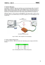
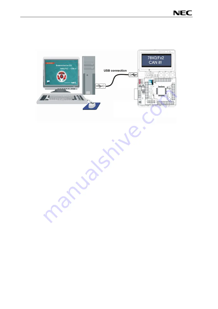
system configuration is given in the diagram below:
Figure 1:
78K0/Fx2 – CAN it!
system configuration
2.1
78K0/Fx2 – CAN it!
78K0/Fx2 – CAN it!
is a demonstration kit for the 78K0/FF2 8-Bit microcontroller. The
78K0/Fx2 – CAN it!
board is connected to the host system via USB interface cable. The host system may be used for On-
Board debugging of application software by using the IAR C-SPY debugger or the programming of the
78K0/FF2 internal FLASH memory by using the FPL3 programming GUI, to allow execution of application
programs on the
78K0/Fx2 – CAN it!
starterkit hardware.
78K0/Fx2 – CAN it!
runs the microcontroller at 12.0000 MHz operating speed. Sub-clock is provided with
32.768 kHz.
2.2 Host computer
The USB host interface enables communication to the
78K0/Fx2 – CAN it!
board. The USB UART chip
FT232 allows application software to access the USB device in the same way as it would access a
standard RS232 interface. The FTDI's Virtual COM Port (VCP) driver appears to the windows system as
an extra Com Port, in addition to any existing hardware Com Ports.
2.3 Power supply via USB interface
78K0/Fx2 – CAN it!
is powered by USB interface, no separate power supply is needed. The USB
interface provides the
78K0/Fx2 – CAN it!
board with 5V supply voltage
.
12


