78K0/Fx2 – CAN it!
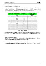
3.9 Display D1, 12*2 character LC display
The
78K0/Fx2 – CAN it!
board is equipped with a character LC display. The display font is equal to 12
character words at 2 lines. The LCD module contains about a character generator ROM - including
predefined standard characters - and a character RAM where the user can define its own characters. The
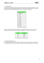
display is connected to the 78K0/FF2 device via three control lines and eight data lines.
Display Pin
Display Signal
Port 78K0/FF2
78K0/Fx2- CAN it!
baseboard
1 Vss
-
GND
2 Vcc
-
Vcc
3
V0
-
R7 potentiometer arm
4 RS P66
-
5 R/W P65
-
6 E P64
-
7 DB0 P40
-
8 DB1 P41
-
9 DB2 P42
-
10 DB3 P43
-
11 DB4 P44
-
12 DB5 P45
-
13 DB6 P46
-
14 DB7 P47
-
15 A
-
Vcc
via
diode
Table 10: Display connections
For more details about the LC display specification, commands and character table, please refer to the
corresponding User’s Manual “WH1202A-NFA-ET.pdf” located in the
/doc
folder of the
78K0/Fx2 – CAN
it!
.
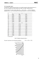
3.10 External Potentiometer R14
A 47K potentiometer R14 is connected between Vcc and ground. The potentiometer arm is connected to
port P80 of 78K0/FF2 device. This is equal to the ANI0 analogue input.
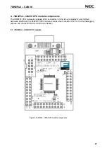
3.11 AD converter reference voltage input
A 1.2V reference voltage is supplied to the ANI1 analogue input, equal to port P81 of 78K0/FF2 device.
18


