background image


13 

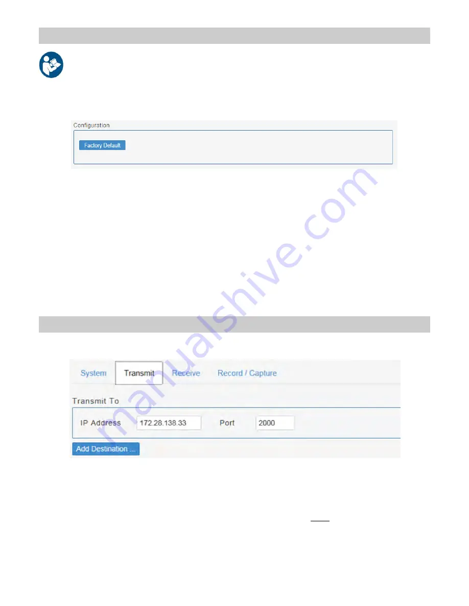
Transmit Tab 

The 

Transmit Tab 

contains configuration parameters related to the output video stream. 

Transmit To: 

IP Address

Enter IP address of the receiver. 

Port

Enter port number of the receiver. 

Note

: Transmit and receive port numbers on the transmitting device must be different to enable 

both streaming transmission and reception. 

Click 

Add Destination

 for configuration of up to two additional destinations for the video stream. To remove 

an added destination, click the 

X

 button. See 

Configuring ExpandOR Multi Node Streaming

 on page 21. 

Restore Factory Defaults 

There are two ways to reset the ExpandOR to factory default settings: 


1.  Using the Web Interface 

Click the Factory Default button in the Device Management Configuration panel. 

Note: You will need to restart the system after performing this operation for the changes to take effect. 

2.  Using the Front Panel  

When the Web Interface is not available or convenient, the ExpandOR may be reset using the Front Panel but-
tons. To reset using the Front Panel buttons:


1.  Power up the ExpandOR. 
2.  Wait for the 

CAPTURE STILL

 LED to illuminate. 

3. While 

the 

CAPTURE STILL 

LED is on, press and hold the 

CAPTURE STILL

 button until the 

RECEIVE

 LED illumi-

nates. The 

RECEIVE

 LED turns off about 10 seconds later. 

4.  All LEDs are off for about 10 seconds. 
5. The 

CAPTURE STILL 

LED illuminates for about 5 seconds, then turns off. 

6.  About 30 seconds after the 

CAPTURE STILL 

LED turns off, all of the Front Panel LEDs will flash. 

7. 

Factory defaults for the ExpandOR are now restored.


Summary of Contents for ExpandOR

Page 1: ...ExpandOR Medical Grade Video Streaming System INSTALLATION GUIDE ENGLISH ...

Page 2: ......

Page 3: ...without notice NDS provides this information as reference only Reference to products from other vendors does not imply any recommendation or endorsement This document contains proprietary information protected by copyright No part of this manual may be reproduced by any mechanical electronic or other means in any form without prior written permission of NDS All trademarks are the property of their...

Page 4: ......

Page 5: ... 16 ExpandOR to ExpandOR Streaming 16 Configuring ExpandOR to ExpandOR Streaming 17 Simultaneous Transmit Receive Operation 17 ExpandOR Streaming to ViewOR 18 ExpandOR Multi Node Streaming 20 Configuring ExpandOR Multi Node Streaming 21 ExpandOR Multicast Streaming 22 Section 8 Front Panel Control 23 GPI Interface Control 23 Web Interface Control 24 Transmit Operation 25 Receive Operation 26 Simul...

Page 6: ...cations are allowed This equipment system is intended for use by healthcare professionals only Safety Compliance This product is T U V approved with respect to electric shock fire and mechanical hazards only in accordance with CAN CSA C22 2 NO 60601 1 and ANSI AAMI ES60601 1 Safety Compliance This product meets the requirements of EN60601 1 so as to conform to the Medical Device Directive 93 42 EE...

Page 7: ...s appropriate they reserve all patent copyright and other proprietary rights to this document including all design manufacturing reproduction use and sales rights thereto except to the extent said rights are expressly granted to others FCC and Council Directives of European Standards This device complies with Part 15 of FCC rules and 93 42 EEC of the Council Directives of European Standards Direct...

Page 8: ......

Page 9: ...urposes or send sample images to a Pathology lab NDS recommends that the initial setup is done in a hospital IT department by a technician with a basic understanding of networking including an understanding of TCP IP protocol IP address gateway subnet mask network port pinging a device on the same network and configuring a laptop to work in a corporate hospital network After initial setup the IT D...

Page 10: ...eway Subnet Mask Network Port Pinging a device on the same network configuring a laptop to work in a corporate hospital network For mission critical applications we strongly recommend that a replacement unit be immediately available General Information Installation ExpandOR units may be stacked on an equipment carrier a surgical cart or mounted in a standard 19 rack Do not block the air vents Powe...

Page 11: ...st the adapter 1 8 turn toward the OPEN arrow and lift it from the power supply Select one of the provided wall adapters Align the tabs on the bottom of the adapter with the notches on the power supply and place the adapter on the power supply Press the adapter down and twist it toward the LOCKarrow until it clicks into place Open the shipping box remove the items listed above and place them on th...

Page 12: ...ed to an audio amplifier DVI IN DVI OUT and Y C OUT video connectors Note Y C S Video RS 232 Serial communication port The RS 232 port is for NDS use only USB Used to install firmware upgrades capture still images and to record the video stream GPI General Purpose Interface allows specific ExpandOR functions to be controlled remotely IP Ethernet connector The video stream is transmitted to and rec...

Page 13: ...OR in the location where it will be used Connect all required devices for this application per the illustrations on page 4 and as shown below System Connections Example DVI In DVI Video Source Video and still image storage Y C Out DVI Out Audio Network Privacy Record Video Capture Still GPI Control RS 232 connector for NDS use only ...

Page 14: ...ndORs connected your network In order to access the Web Interface CruzOR must be installed on the same subnet as the ExpandOR 1 Place the included CruzOR utility CD in the PC CD or DVD drive 2 Double click the Setup file to open the CruzOR Setup Wizard 3 Follow the onscreen instructions ...

Page 15: ...ates Note If the ExpandOR is being re installed or relocated from another network It is recommended that the factory defaults are restored before proceeding See Restore Factory Defaults Using the Front Panel on page 13 for more information 5 6 All LEDs are off for about 10 seconds 7 The CAPTURE STILL LED illuminates for about 5 seconds then turns off 5 The RECEIVE LED illuminates on for about 10 s...

Page 16: ...und on other subnets are highlighted in red as shown below and will not be configurable from the current subnet Only ExpandORs on the same subnet as CruzOR can access the Web Interface from CruzOR 6 The MAC Addresses and IP Addresses used in this manual are for example only Double click the icon shown below to launch the CruzOR utility 3 Select the ExpandOR to be configured The selected ExpandOR i...

Page 17: ...vice See Login under Device Management on page 12 After logging in the ExpandOR Web Interface opens displaying the Operations Front Panel section The Web Interface is divided into 4 main sections 1 Operations 2 Configuration 3 Storage 4 Logout The sections are accessible from the links in the upper right corner of the Web Interface Web Interface Operations The five Operations Front Panel functions...

Page 18: ...g layer to determine what addresses are within the subnet and which are in a separate subnet Default Gateway Default gateway of the network which is used for routing IP packets outside of the current subnet Use DHCP Uncheck this option to allow the network fields to be edited for a static IP address Note After changing the local network settings the ExpandOR must be restarted to implement the new ...

Page 19: ...ed to prevent issues encountered with displays that are unable to detect seamless mode switching The default DVI Output Display Reset setting unchecked provides the fastest DVI output switching with the least amount of flickering With this setting the DVI output timings change seamlessly to accommodate different video streams but may cause incorrect signal detection with some monitors When the DVI...

Page 20: ...ve button The updated device name will be displayed in the right top corner of the web interface MIC Gain Microphone gain may be adjusted by entering a higher or lower percentage from 1 to 100 NTP Server IP An NTP Network Time Protocol server may be specified for the ExpandOR to synchronize its clock Time synchronization occurs at each boot up Upload System Image An ExpandOR System Image in the ex...

Page 21: ...erface Click the Factory Default button in the Device Management Configuration panel Note You will need to restart the system after performing this operation for the changes to take effect 2 Using the Front Panel When the Web Interface is not available or convenient the ExpandOR may be reset using the Front Panel but tons To reset using the Front Panel buttons 1 Power up the ExpandOR 2 Wait for th...

Page 22: ... stream configuration parameters include Video Resolution Select a video resolution for the video stream Audio Select On or Off options for inclusion of audio in the output video stream Video Bit Rate Specify compression bit rate of the output video stream Click the Save button to apply the configuration Notes 1 Image quality requires a balance between Video Resolution and Video Bit Rate Higher re...

Page 23: ...ansport Stream ts format to a predetermined Video folder of the selected USB drive its files can be opened with the VLC media player Notes 1 USB drives used with ExpandOR must be formatted to FAT32 2 The FAT 32 system has file size limit of 4GB If the recording file exceeds that size a new file will be created with same name prefix but with a new date time stamp 3 If a precise time stamp on captur...

Page 24: ...its video and audio signals can travel The ExpandOR signal capabilities are constrained by the device with which it is communicating Configuring a pair of ExpandORs for one way and two way communications is described on the next page ExpandOR to ExpandOR Streaming From ExpandOR Signal Direction Transmit Yes Receive Yes Both Yes To ExpandOR Signal Direction Transmit Yes Receive Yes Both Yes ...

Page 25: ...ess in the IP address window in the Transmit To group box Port Specify the transmit port e g 5004 ExpandOR B receiving from ExpandOR A Click the Receive tab of the second ExpandOR set the following parameters Simultaneous Transmit Receive Operation The procedure described above may be used to configure simultaneous two way transmit receive operation between two ExpandOR units Different port number...

Page 26: ... to configure the ExpandOR to transmit to a computer running the ViewOR player In this case the computer IP address is 172 28 138 33 and the ExpandOR s IP address is 172 28 138 146 IP Address Enter IP address of the receiving computer e g 172 28 138 33 Port Enter port number of the receiving computer Click the Save button and then click the Web Interface Transmit button on the Operations page or p...

Page 27: ...dia dialog 2 Click the Networktab in the Open Media menu and select HTTP from the Protocol dropdown menu 3 Enter the transmitting ExpandOR IP address into the Address field 4 Click the Play button at the bottom right of the Open Media menu 5 Press the ExpandOR Front Panel TRANSMIT button 6 The video stream will begin displaying in the ViewOR window ...

Page 28: ... Yes Receive Yes Both Yes To ExpandOR A To ExpandOR C ExpandOR Multi Node Streaming 1 Multi Node operation supports a maximum of three ExpandOR units as shown below 2 As shown below only one of the receiving units may be configured for transmit receive operation The two other receiving units must be configured to receive only Configuring an ExpandOR for Multi Node operation is described on the nex...

Page 29: ...cify the transmit port e g 5004 3 Click the Add Destination button as shown to add the second destination 5 IP Address Enter the receiver IP address in the IP address window under Transmit To 6 Port Specify the transmit port e g 5004 7 Click the Add Destination button as shown to add the third destination The Add Destination button is now disabled 8 IP Address Enter the receiver IP address in the ...

Page 30: ...e an ExpandOR is configured to transmit to a multicast IP address e g 239 1 2 3 over port 2000 ExpandOR Multicast Streaming Multiple receiving ExpandOR s may then be configured to receive the stream from the same multicast IP address and port number 239 1 2 3 2000 Transmitter Signal Direction Transmit Yes Receive No Both No Receivers Signal Direction Transmit No Receive Yes Both No Receiver Settin...

Page 31: ...ch time the CAPTURE STILL button is clicked Function LED State Description TRANSMIT On Unit is transmitting data to the network RECEIVE On Unit is receiving data from the network PRIVACY On Privacy is enabled RECORD VIDEO On Video is being recorded CAPTURE STILL Flash Captures the current video frame See Web Interface Control on pages 24 31 for detailed information about these functions Control vi...

Page 32: ...ations Front Panel page shown below is displayed To return to or refresh the Front Panel page click on the Operations tab at the top right of the page Web Interface Control Note For operations shown on this page to function properly ExpandOR transmit parameters receive parameters and local network settings must be correctly configured ...

Page 33: ...o signal over the network using the ExpandOR Web Interface click on the Transmit button The Transmit state changes from Idle to Pending and finally to Running and the Transmit indicator will be green If no error is shown in the Web Interface and the Transmit indicator remains green then ExpandOR is transmitting the video stream to the configured destination or destinations Transmit Operation ...

Page 34: ...nal from the network using the ExpandOR Web Interface click on the Receive button The Receive state changes from Idle to Pending and finally to Running and the Receive indicator will be green If no error is shown in the Web Interface and the Receive indicator remains green then ExpandOR is transmitting the video stream to the configured destination or destinations Receive Operation ...

Page 35: ...n simultaneously transmit and receive video and audio To begin simultaneous transmit and receive press both Front Panel TRANSMIT and RECEIVE buttons or click both Transmit and Receive buttons on the Web Interface Simultaneous Transmit and Receive Operation ...

Page 36: ...d audio To enable or disable the Privacy function press the ExpandOR Front Panel PRIVACY button or click the Web Interface Privacy button or trigger the Privacy pin on the GPI fixture Note Privacy does not affect the local DVI or S VIDEO outputs Privacy Feature Note HIPAA is the Health Insurance Portability and Accountability Act which sets the standard for pro tecting sensitive patient data ...

Page 37: ...ed as a jpg file in the image folder of the selected USB drive See View Captured Image and Recorded Video Lists on page 31 for detailed information about storage functions To enable the Capture Still function press the Front Panel CAPTURE STILL button or click the Capture Still button on the Web Interface or trigger the Capture Still pin on the GPI fixture The Front Panel CAPTURE STILL LED will bl...

Page 38: ...function press the Front Panel RECORD VIDEO button or click the Record Stream button on the Web Interface or trigger the Record pin on the GPI fixture The Front Panel RECORD VIDEO LED and the Web Interface Record Stream indicator will be green throughout the recording operation If the available free disk space drops below 200 MB both the Front Panel RECORD VIDEO LED and the Web Interface Record St...

Page 39: ...ted via USB hubs and USB drives with multiple partitions If there are multiple drives available these will be listed in the Available storage list dropdown menu View Captured Image and Recorded Video Lists To safely eject the USB drive click the Eject button then remove the USB drive from the USB port The Image List and Video List group boxes list the files currently stored on the selected USB dri...

Page 40: ...ages are captured correctly A list of recorded videos and captured images is available in the storage panel of the web interface Note You need to refresh every time to check for new files Can I record videos more than 4GB of size Maximum file size restriction on FAT32 is 4 GB When the file size exceeds that limit ExpandOR automatically creates a new file and will continue to store 4GB files until ...

Page 41: ...e sizes for each available bitrate setting What is the resolution of a captured still from a recorded video stream The captured still file is stored at the resolution of the stream being sent or received the compression rate is fixed and the file size depends on the stream resolution and image being processed Can I connect VGA output to ExpandOR s DVI IN port VGA signals and analog DVI signals are...

Page 42: ...34 Drawing and Dimensions 10 ...

Page 43: ...r Chrominance PIN SIGNAL PIN SIGNAL 1 T M D S DATA 2 16 HOT PLUG DETECT 2 T M D S DATA 2 17 T M D S DATA 0 3 T M D S DATA 2 4 SHIELD 18 T M D S DATA 0 4 T M D S DATA 4 19 T M D S DATA 0 5 SHIELD 5 T M D S DATA 4 20 T M D S DATA 5 6 DDC CLOCK 21 T M D S DATA 5 7 DDC DATA 22 T M D S CLOCK SHIELD 8 23 T M D S CLOCK 9 T M D S DATA 1 24 T M D S CLOCK 10 T M D S DATA 1 11 T M D S DATA 1 3 SHIELD 12 T M ...

Page 44: ...onnector is used to install firmware upgrades and to capture still images or to record the video stream Pin Name Description 1 VCC 5 VDC 2 D Data 3 D Data 4 GND Ground USB Connector Pin Name Description 1 Privacy Turns Privacy on or off 2 Record Video Turns video recording on or off 3 Capture Still Captures the current video frame 4 GND Common Ground GPI Mating Connector RJH 4 Pin Telephone Handse...

Page 45: ...59 1920x1080p 30 Hz 1080p30 1920x1080p 24 Hz 1080p24 1920x1080p 23 98 Hz 1080p23 1920x1080p 29 97 Hz 1080p29 1920x1080p 25 Hz 1080p25 1280x720p 60 Hz 720p60 1280x720p 59 94 Hz 720p59 1280x720p 50 Hz 720p50 1280x720p 30 Hz 720p30 1280x720p 29 97 Hz 720p29 1280x720p 25 Hz 720p25 Progressive Video Resolutions Resolution Generator Mode 1920x1080i 60 Hz 1080i60 1920x1080i 50 Hz 1080i50 1920x1080i 59 94...

Page 46: ...lint free cloth dampened with 80 Ethyl Alcohol Allow the unit to air dry Cautions Do not allow liquids to enter the interior of the unit and do not permit exterior surfaces to come into contact will unacceptable solvents such as those listed below as severe damage to the unit may result Acceptable Cleaning Materials Vinegar distilled white vinegar 5 acidity Ammonia based glass cleaner Acceptable D...

Page 47: ...e relative humidity should be at least 30 Electrical fast transient burst IEC 61000 4 4 2 kV for power supply lines 2 kV for power supply lines Mains power quality should be that of a typical commercial or hospital environment Surge IEC 61000 4 5 1 kV line s and neutral 1 kV line s and neutral Mains power quality should be that of a typical commercial or hospital environment Voltage dips short int...

Page 48: ...ters as determined by an electromagnetic site survey a should be less than the compliance level in each frequency range b Interference may occur in the vicinity of equipment marked with the following symbol NOTE 1 At 80 MHz and 800 MHz the higher frequency range applies NOTE 2 These guidelines may not apply in all situations Electromagnetic propagation is afjected by absorption and re ection from ...

Page 49: ...wer W of transmitter Separation distance in meters according to frequency of transmitter 150 kHz to 80 MHz 80 MHz to 800 MHz 800 MHz to 2 5 GHz 0 01 0 12 0 12 0 23 0 1 0 38 0 38 0 73 1 1 2 1 2 2 3 10 3 8 3 8 7 3 100 12 12 23 For transmitters rated at a maximum output power not listed above the recommended separation distance d in meters m can be estimated using the equation applicable to the frequ...

Page 50: ......

Page 51: ......

Page 52: ...many 49 89 31 707 100 info novanta europe novanta com Asia Pacific Novanta Japan East Square Omori 6 20 14 Minamioi Shinagawa ku Tokyo 140 0013 Japan 81 3 5753 2466 info ndssi jp Oriental Media Center Suite 2302 Tower C No 4 Guang Hua Road Chao Yang District Beijing 100026 China 86 10 8559 7859 info ndssi com cn NDS Quality System ISO 9001 2008 and ISO 13485 2003 FDA Registration 2954921 ...

Reviews: