


7156 Service Guide
Chapter 2: Setting Up the Printer
September 1998
11
Setting DIP Switches
The DIP switches, located behind the front cover, are used for three purposes:
•
To set communication parameters for the RS-232C communication interface (see
Appendix B for the switch settings)
Or
to set address bits for the LCSIO (RS-485) communication interface (see Appendix B for
the switch settings)
•
To set variables for several printer functions (see the sections for the various printer
functions in “Level 1 Diagnostics” in “Chapter 3: Diagnostics” for the switch settings)
•
To perform diagnostic tests (see the sections for the various diagnostic tests in “Level 1
Diagnostics” in “Chapter 3: Diagnostics” for the switch settings)
Caution:
The DIP switches are set at the factory to predetermined settings and should
generally not be changed. If you must change the settings do so carefully to avoid
changing other functions.
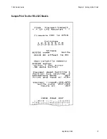
Before changing any of the switches, first run the print test to print out the current switch
settings on the receipt. See “Testing the Printer” at the end of this chapter for instructions
on running the print test and for a sample printout.
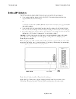
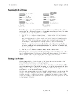
Front of Printer
Reset
Button
Front Cover
Off
Switch 1 is shown
in the OFF position
On
DIP Switch
Note:
Switch 1 is shown in the off position for reference.
Note:
Some 7156 models may appear slightly different from what is shown in the
illustration. The procedures are the same for all models unless otherwise noted.
Summary of Contents for 7156
Page 16: ......
Page 20: ...Chapter 1 About the 7156 Printer 7156 Service Guide September 1998 6...
Page 34: ...Chapter 2 Setting Up the Printer 7156 Service Guide September 1998 20...
Page 72: ...Chapter 5 Adjustments 7156 Service Guide September 1998 58...
Page 79: ...7156 Service Guide Chapter 6 Removing the Thermal Receipt Mechanism September 1998 65...
Page 81: ...7156 Service Guide Chapter 6 Removing the Thermal Receipt Mechanism September 1998 67...
Page 99: ...7156 Service Guide Chapter 8 Replacing the Thermal Receipt Mechanism September 1998 85...
Page 101: ...7156 Service Guide Chapter 8 Replacing the Thermal Receipt Mechanism September 1998 87...
Page 108: ......
Page 154: ......
Page 158: ...Chapter 15 Removing the Base Feed Mechanism 7156 Service Guide September 1998 144...
Page 164: ...Chapter 16 Forms Compensation Arm Assembly 7156 Service Guide September 1998 150...
Page 172: ...Chapter 18 Solenoid and Pivot Arm Assemblies 7156 Service Guide September 1998 158...
Page 178: ......
Page 198: ...Appendix D Ordering Paper and Supplies 7156 Service Guide September 1998 184...
Page 204: ...Index 7156 Service Guide September 1998 190...
Page 205: ......


