


Service Manual Chapter7. Cash Dispenser Unit
© 2013
Nautilus Hyosung Inc.
All Rights Reserved.
7-5
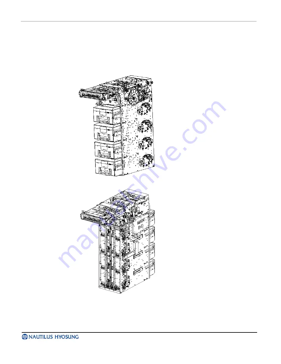
Types
► The standard type in this cash dispenser is the front access cash dispenser with four
cassettes and no shutter on the body. However, this cash dispenser can be supported
with a lot of optional types as the direction of presenter, the availability of shutter and
the number of cassette will be changed, as shown the below pictures.
1. Front access type
2. Rear access type


