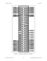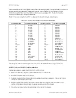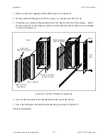
SCXI-1120 Front Connector
Appendix D
SCXI-1120 User Manual
D-2
© National Instruments Corporation
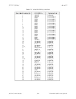
Front Connector Signal Descriptions
Pin
Signal Name
Description
A2
CHSGND
Chassis Ground – Tied to the SCXI chassis.
C2
DTEMP
Direct Temperature Sensor – Connects the
temperature sensor to pin 18 of the rear signal
connector MCH7- when the terminal block is
configured for direct temperature connection and
jumper W41 is in position 3.
A4
+5 V
+5 VDC Source – Used to power the temperature
sensor on the terminal block. 0.2 mA of source not
protected.
C4
MTEMP
Multiplexed Temperature Sensor – Connects the
temperature sensor to the output multiplexer.
A6, C6, C8
RSVD
Reserved – Reserved for future use. Do not connect
any signals to these pins. TTL/CMOS output. They
are not protected.
A8, A10, C10,
No Connect
Do not connect any signals to these pins.
A16, C16,A22,
C22, A28, C28
A12, A14, A18, CH7+ through CH0+
Positive Input Channels – The positive inputs to
A26, A20, A24,
channels 7 through 0, respectively.
A30, A32
C12, C14, C18, CH7- through CH0-
Negative Input Channels – The negative inputs to
C20, C24, C26,
channels 7 through 0, respectively.
C30, C32
Further information is given in Chapter 2, Configuration and Installation.

