


SCXI-1120 Cabling
Appendix E
SCXI-1120 User Manual
E-4
© National Instruments Corporation
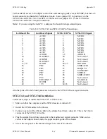
Lab boards full access to the digital control lines and analog signals (except DTEMP), but the Lab
boards cannot scan channels in Multiplexed mode. Leave jumper W1 in position A on the
SCXI-1341 and SCXI-1344. The SCXI-1120 does not use jumper W1. Table E-2 lists the
SCXI-1341 and SCXI-1344 pin translations.
Note: If you are using the Lab-PC+, configure the board for single-ended inputs.
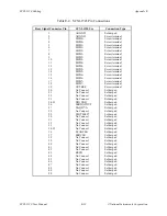
Table E-2. SCXI-1341 and SCXI-1344 Pin Translations
Lab Board Pin
Lab Board Signal
SCXI-1120 Pin
SCXI-1120 Signal
1
ACH0
3
MCH0+
2
ACH1
5
MCH1+
3
ACH2
7
MCH2+
4
ACH3
9
MCH3+
5
ACH4
11
MCH4+
6
ACH5
13
MCH5+
7
ACH6
15
MCH6+
8
ACH7
17
MCH7+
9
AIGND
1-2
AOGND
10
DAC0OUT
20
No Connect
11
AOGND
23
No Connect
12
DAC1OUT
21
No Connect
13, 50
DGND
24, 33
DIG GND
26
PB4
25
SERDATIN
27
PB5
27
DAQD*/A
28
PB6
29
SLOT0SEL*
29
PB7
37
SERCLK
31
PC1
26
SERDATOUT
32
PC2
28
No Connect
40
EXTCONV*
36
SCANCLK
43
OUTB1
46
No Connect
49
+5 V
34-35
No Connect
All other pins of the Lab board pinout are not sent to the SCXI-1120 rear signal connector.
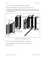
SCXI-1341 and SCXI-1344 Installation
Follow these steps to install the SCXI-1341 or SCXI-1344:
1. Make sure that the computer and the SCXI chassis are turned off.
2. Install the SCXI module in the chassis.
3. Connect one end of the ribbon cable to the adapter board rear connector. This is the 50-pin
connector of the SCXI-1344 cable.
4. Plug the adapter board front connector to the module rear signal connector. Make sure a
corner of the adapter board enters the upper module guide of the chassis.
5. Screw the rear panel to the threaded strips in the rear of the chassis.


