Configuration and Installation
Chapter 2
SCXI-1120 User Manual
2-10
© National Instruments Corporation
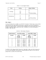
Table 2-5. Gain Jumper Positions
Gain
Setting
Jumper Position
First-stage
1
10
50
100
D
C
B
A (Factory setting)
Second-stage
1
2
5
10
20
A
B
C
D (Factory setting)
E
Filter Jumpers
Two-stage filtering is also available on your SCXI-1120 module. The first stage is located in the
isolated section of the input channel, whereas the second stage is located in the nonisolated
section of your input channel. Two-stage filtering eliminates the noise generated by the isolation
amplifier, producing a higher signal-to-noise ratio. Furthermore, two filter bandwidths are
available, 10 kHz and 4 Hz.
Table 2-6. Filter Jumper Allocation
Input Channel
First Filter Jumper
Second Filter Jumper
Number
4 Hz
(Factory
Setting)
10 kHz
4 Hz
(Factory
Setting)
10 kHz
0
W17-A
W17-B
W25
W26
1
W18-A
W18-B
W27
W28
2
W19-A
W19-B
W29
W30
3
W20-A
W20-B
W31
W32
4
W21-A
W21-B
W33
W34
5
W22-A
W22-B
W35
W36
6
W23-A
W23-B
W37
W38
7
W24-A
W24-B
W39
W40
Your SCXI-1120 is shipped in the 4 Hz position. Remember to make sure that both stages are
set to the same bandwidth to ensure that the required bandwidth is achieved. Notice that one
jumper block is available for each filter stage.


