


SCXI-1120 Cabling
Appendix E
SCXI-1120 User Manual
E-2
© National Instruments Corporation
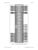
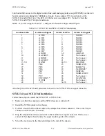
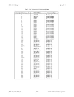
Table E-1 lists the pin equivalences of the MIO-16 board and the SCXI-1120.
Table E-1. SCXI-1120 and MIO-16 Board Pinout Equivalences
Pin
SCXI-1120 Rear Signal Connector
MIO-16 Board
Equivalent
1-2
AOGND
AIGND
3
MCH0+
ACH0
4
MCH0-
ACH8
5
MCH1+
ACH1
6
MCH1-
ACH9
7
MCH2+
ACH2
8
MCH2-
ACH10
9
MCH3+
ACH3
10
MCH3-
ACH11
11
MCH4+
ACH4
12
MCH4-
ACH12
13
MCH5+
ACH5
14
MCH5-
ACH13
15
MCH6+
ACH6
16
MCH6-
ACH14
17
MCH7+
ACH7
18
MCH7-
ACH15
19
OUTREF
AISENSE
24, 33
DIG GND
DIG GND
25
SERDATIN
ADIO0
26
SERDATOUT
BDIO0
27
DAQD*/A
ADIO1
29
SLOT0SEL*
ADIO2
36
SCANCLK
SCANCLK
37
SERCLK
EXTSTROBE*
43
RSVD
OUT1
No other pins are connected on the SCXI-1120.
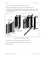
SCXI-1340 Installation
Follow these steps to install the SCXI-1340:
1. Make sure that the computer and the SCXI chassis are turned off.
2. Install the SCXI module in the chassis.
3. Plug the mounting bracket connector onto the module rear signal connector (see Figure E-1).
Make sure the alignment tab on the bracket enters the upper module guide of the chassis.
4. Screw the mounting bracket to the threaded strips in the rear of the chassis.


