Appendix E
SCXI-1120 Cabling
© National Instruments Corporation
E-11
SCXI-1120 User Manual
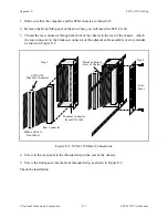
5. Connect another ribbon cable or cable assembly to the chassis extender connector.
6. Plug the adapter board front connector to the module rear signal connector. Make sure a
corner of the adapter board enters the upper module guide of the chassis.
7. Screw the rear panel to the threaded strips in the rear of the chassis.
8. Connect the cable assembly to the desired module in the second chassis, or if you are using
more than two chassis, connect the loose end of the ribbon cable to the rear connector of the
second SCXI-1350, and install the adapter board.
9. Continue until all chassis are connected. For N chassis, you will need N ribbon cables and N
multichassis adapters.
SCXI-1343 Rear Screw Terminal Adapter
You use the SCXI-1343 universal adapter to adapt custom wiring to the SCXI-1120. The
SCXI-1343 has screw terminals for the analog output connections and solder pads for the rest of
the signals. A strain-relief clamp is on the outside of the rear panel.
SCXI-1343 Installation
1. Insert each wire through the adapter strain-relief opening.
2. Make all solder connections first.
3. Connect the other wires to the screw terminals.
4. Tighten the strain-relief screws to secure the wires.
5. Plug the adapter board front connector to the module rear signal connector. Make sure a
corner of the adapter board enters the upper module guide of the chassis.
6. Screw the rear panel to the threaded strips in the rear of the chassis.


