Appendix E
SCXI-1120 Cabling
© National Instruments Corporation
E-5
SCXI-1120 User Manual
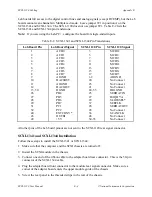
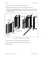
6. For an SCXI-1341, connect the loose end of the ribbon cable to the Lab-NB, Lab-PC, or
Lab-PC+ I/O connector. For an SCXI-1344, connect the two 26-pin connectors to the
Lab--LC according to the instructions given in the Installation section of Chapter 2,
Configuration and Installation, of the Lab-LC User Manual.
Check the installation.
SCXI-1342 PC-LPM-16 Cable Assembly
The SCXI-1342 PC-LPM-16 cable assembly connects a PC-LPM-16 board to an SCXI-1120
module. The 1342 cable assembly consists of two pieces–an adapter board and a 50-conductor
ribbon cable that connects the PC-LPM-16 board to the adapter board. The adapter board
converts the signals from the PC-LPM-16 I/O connector to a format compatible with the
SCXI-1120 rear signal connector pinout. The adapter board also has an additional male breakout
connector that makes the unmodified PC-LPM-16 signals accessible to an SCXI-1180
feedthrough panel or SCXI-1181 breadboard module. The adapter board gives the PC-LPM-16
full access to the digital control lines and analog signals, but the PC-LPM-16 cannot scan
channels in the Multiplexed mode. Leave jumper W1 in position A on the SCXI-1342. The
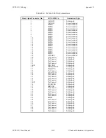
SCXI-1120 does not use jumper W1. Table E-3 lists the SCXI-1342 pin translations.
Table E-3. SCXI-1342 Pin Translations
PC-LPM-16 Pin
PC-LPM-16 Signal
Rear Signal
Connector Pin
SCXI-1120 Use
1-2
AIGND
1-2
AOGND
3
ACH0
3
MCH0+
4
ACH8
4
MCH0-
5
ACH1
5
MCH1+
6
ACH9
6
MCH1-
7
ACH2
7
MCH2+
8
ACH10
8
MCH2-
9
ACH3
9
MCH3+
10
ACH11
10
MCH3-
11
ACH4
11
MCH4+
12
ACH12
12
MCH4-
13
ACH5
13
MCH5+
14
ACH13
14
MCH5-
15
ACH6
15
MCH6+
16
ACH14
16
MCH6-
17
ACH7
17
MCH7+
18
ACH15
18
MCH7-
19, 50
DGND
24, 33
DIG GND
28
DIN6
26
SERDATOUT
29
DIN7
28
No Connect
34
DOUT4
25
SERDATIN
35
DOUT5
27
DAQD*/A
(continues)

