Theory of Operation
Chapter 3
SCXI-1120 User Manual
3-10
© National Instruments Corporation
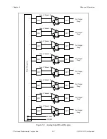
The analog input consists of eight isolated single-ended noninverting amplifiers. In addition,
lowpass filtering is available at the inputs. You can jumper select one of two bandwidths,
10 kHz or 4 Hz. The amplifier gain is divided into two stages, a first stage providing gains of 1,
10, 50, and 100, and a second stage providing gains of 1, 2, 5, 10, and 20. Each channel is
configurable to a different bandwidth and gain.
Use the following formula to determine the overall gain of a given amplifier input channel:
G
total
= G
1st
x G
2nd
where G
total
is the overall gain and G
1st
and G
2nd
are the first- and second-stage gains. Here it is
important to note that the choice of gain in each stage will affect the amplifier bandwidth. To
determine the bandwidth of a given gain stage use the following formula:
BW = GBWP/G
where BW is a given amplifier stage bandwidth, GBWP is the gain bandwidth product (typically
800 kHz), and G is the gain at this stage. This BW might be of concern at high first-stage gains
such as 50 and 100. In this case, the first-stage amplifier has a BW equal to 16 kHz and 8 kHz,
respectively. Due to this decrease in the amplifier bandwidth, you will notice a decrease in the
channel overall bandwidth, but a better noise immunity. If this bandwidth limitation is
unacceptable, you should spread the gains over both stages, thus increasing the BW of each
amplifier stage. This will introduce, in most cases, a negligible effect on the channel bandwidth.
For example, to achieve a gain of 100, use G
1st
= 10 and G
2nd
= 10; for a gain of 1,000, use
G
1st
= 50 and G
2nd
= 20.
All the amplifier input channels are overvoltage protected to 240 Vrms with power on or off.
The isolated amplifiers fulfill two purposes on the SCXI-1120 module. They convert a small
signal riding on a high common-mode voltage into a single-ended signal with respect to the
SCXI-1120 chassis ground. With this conversion, the input analog signal can be extracted from
a high common-mode voltage or noise before being sampled and converted by the data
acquisition board. The isolated amplifier also amplifies and conditions an input signal, which
results in an increase in measurement resolution and accuracy.
After isolation, further filtering is available to increase the noise immunity of the amplifier
channel. It is important to note that the overall amplifier bandwidth is determined by both
filtering stages, so to achieve the required bandwidth, both filtering sections should be set the
same, as indicated in Chapter 2, Configuration and Installation.
Calibration
Calibration Equipment Requirements
For best measurement results, calibrate the SCXI-1120 so that its offset is adjusted to 0
±
3 mV
RTO and 0
±
6
µ
V RTI. No special equipment is needed other than a regular voltmeter with the
following specifications.
•
Range:
±
30 mV to
±
300 mV
•
Resolution:
3 1/2 digits or greater


