background image

Chapter 8 Applications for GVWIN

8-14

Creating a New SIM File

The procedure for creating a new SIM file is described below.  When a new file is 
created, you can set the memory that is displayed on the sheet as you wish.  
You can also choose the SIM file name.  It is possible to create a new SIM file 
even when an automatically created SIM file, or an SIV-based SIM file, is 
already displayed on the personal computer.

1. Go to the [File] menu and click on [New...].  Or, click on the [New (Word)] 

icon on the tool bar.

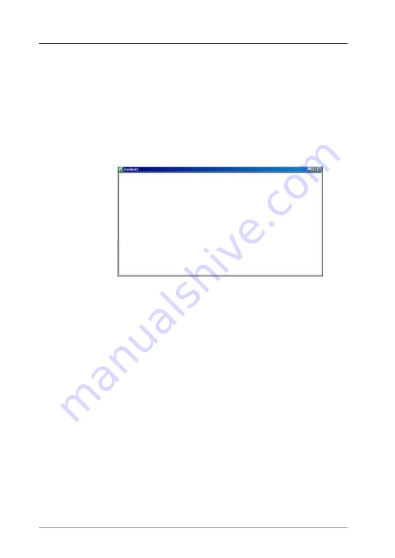
2. A sheet with the title [Untitled x] is displayed.  Add or insert the memory that 

you wish to test.

Saving a Newly Created SIM File

The procedure for saving a newly created SIM file is described below.

1. Click on the [File] menu.  There are two options, [Save] and [Save As...].

2. Choosing [Save]:

If this is the first time that you have saved, the [Save As...] dialog will be 
displayed.  Enter a file name and click on [Save].

3. Choosing [Save As...]:

The [Save As...] dialog will be displayed.  Enter a file name and click on 
[Save].

Buy: www.ValinOnline.com | Phone 844-385-3099 | Email: [email protected]

Summary of Contents for GV42C

Page 1: ...ration Applicable Product GV42C GV52S GV62S GV42 52 62 This manual was created using Adobe Acrobat Adobe the Adobe logo and Acrobat are trademarks of Adobe Systems Incorporated Buy www ValinOnline com...

Page 2: ...Buy www ValinOnline com Phone 844 385 3099 Email CustomerService valin com...

Page 3: ...numbers are shown at the bottom left corner on the back cover of each manual Printing Date Reference No Revised Contents April 2003 ACRT1F377 First edition Buy www ValinOnline com Phone 844 385 3099 E...

Page 4: ...Buy www ValinOnline com Phone 844 385 3099 Email CustomerService valin com...

Page 5: ...are subject to change without prior notice 4 If the specifications of the software do not correspond with the contents of this manual the software specifications have priority 5 No liability is assum...

Page 6: ...Name Reference No Contents Reference Manual Operation ARCT1F377 The GVWIN structure operations editing procedure etc required when creating screen data are explained Reference Manual Function ARCT1F3...

Page 7: ...ains the data transfer procedure from the editor Chapter 6 Print This chapter explains the printing procedure from the editor Chapter 7 Useful Techniques This chapter explains useful techniques in edi...

Page 8: ...e used in this manual to attract attention of the reader Describes important information that must be heeded Indicates cross references Describes the reference or supplemental information Generic Name...

Page 9: ...ed in case of emergency Please design the system so that it can cope with malfunction of a touch switch Turn off the power supply when you set up the unit connect cables or perform maintenance and ins...

Page 10: ...rticles are present Avoid installing the unit in a location where vibration or physical shock may be transmitted Equipment must be correctly mounted so that the main terminal of GV will not be touched...

Page 11: ...or injury Read this manual and related manuals carefully and handle the lithium battery correctly as instructed If a data receive error occurs when GV and the counterpart PLC temperature controller et...

Page 12: ...Buy www ValinOnline com Phone 844 385 3099 Email CustomerService valin com...

Page 13: ...on 2 1 Screen Outline 2 1 Screen Structure 2 5 Operation Environment Setting 2 7 Background Color Setting 2 7 Display Environment Setting 2 10 Part Types and Placement 2 17 Part Types 2 17 Notes on Pa...

Page 14: ...57 32 000 color Type 2 58 128 color Type 2 61 Monochrome Type 2 62 Blinking Setting 2 63 Chapter 3 Drawing Tools Tools 3 1 Basic Operations 3 2 Screen Drawing Dialog 3 2 Selecting Colors 3 3 Selectin...

Page 15: ...Data Block Environment Setting 4 27 Message 4 28 Message Structure 4 28 Calling a Message 4 30 Message Editing 4 31 Message Display Environment Setting 4 35 Pattern 4 37 Pattern Structure 4 37 Callin...

Page 16: ...V42C 4 85 Animation Function Structure 4 85 Calling the Animation Function 4 85 Animation Editing 4 86 Frame Editing 4 88 Chapter 5 Transfer Before Using the GV Series 5 1 Preliminary Steps 5 1 Screen...

Page 17: ...tern 7 10 Function 6 Copy Image to Clip Board 7 12 Function 7 Paste Bitmap 7 14 Function 8 DXF File Convert 7 17 Function 9 Convert to Rich Text Format 7 19 Function 10 Add Video Menu 7 21 Function 11...

Page 18: ...ror List 8 31 Chapter 9 Wizard Outline 9 1 Opening the Wizard Dialog 9 1 Wizard Usage Examples 9 2 Radio Button Creation 9 2 Error Display 9 6 Trend Graph Display 9 11 Deleting Placed Parts 9 16 Appen...

Page 19: ...Switch Lamp Parts APP3 9 Editing Data Display Parts APP3 14 Editing a Keypad APP3 15 Editing Graph Parts APP3 17 Editing Display Area Parts for Data Sampling APP3 29 Editing Calendar Parts APP3 31 Ed...

Page 20: ...Buy www ValinOnline com Phone 844 385 3099 Email CustomerService valin com...

Page 21: ...n of the Editor 1 6 Names of Components 1 6 Menu Bar 1 11 Dialog 1 17 Edit Window 1 22 Item List 1 27 Useful Operations 1 30 Useful Editing Commands 1 35 Screen Data File Property 1 42 Chapter 1 Basic...

Page 22: ...Buy www ValinOnline com Phone 844 385 3099 Email CustomerService valin com...

Page 23: ...n procedure see Installation attached to the GVWIN editor Starting Start your computer and check that Windows runs correctly 1 Click the Start button of Windows and click Programs GVWIN then GVWIN 2 T...

Page 24: ...odel dialog is displayed Select the model name and click OK 3 The Select PLC Type dialog is displayed Select the PLC model and click OK or For the edit models see Chapter 1 System Setting in the Refer...

Page 25: ...c Operation 1 3 1 RStarting and Quitting Clik OK The Screen 0 Edit window is displayed For more information on the menu items see page 1 7 Buy www ValinOnline com Phone 844 385 3099 Email CustomerServ...

Page 26: ...en from the File menu 2 The Open a Screen Data File dialog is displayed Select the desired screen data file and click the Open button 3 The selected screen data file is opened or For more information...

Page 27: ...the File menu or the Close button 2 The screen is closed If the file has not been saved after changes the following dialog appears and asks whether or not to save the data Click either Yes or No to qu...

Page 28: ...reen edit window is opened Title Bar The title bar contains the following information To minimize the indication on the title bar click Property in the File menu and put a check mark to Shorten the Ti...

Page 29: ...t division number is indicated This number should be used for identifying the division when placing parts or items For more information on the menu items see page 1 11 New File Open Save Transfer Star...

Page 30: ...6 Stat Graph 28 Memo Pad 5 Char Display 17 Trend Graph 29 Macro Mode 6 Message Display 18 Closed Area Graph 30 Interval Timer 7 Table Data Display 19 Graphic Mode 31 Memory Card Mode 8 Relay Mode 20 G...

Page 31: ...Release the mouse button in the desired position The tool bar is moved to the position To alter the shape move the tool bar out on the screen and drag the tool bar edge Each icon has the function sho...

Page 32: ...the tool bar name Status Bar The status bar contains the following information Hiding the Status Bar The status bar is shown as default To hide the status bar uncheck Status Bar in the Tool Bar sub me...

Page 33: ...ine editing On line Run This command becomes active in on line editing When it is clicked only the screen data that has not been transferred yet is transferred to GV Printer Setting Used for printing...

Page 34: ...elected Screen Pastes the copied item to multiple screens For more information see page 1 37 Undo Paste to Selected Screen Cancels the Copy to Selected Screen operation that you performed Delete Delet...

Page 35: ...k this menu The Prop Change dialog is displayed Select Environment For more information see Select Environment page 1 41 Division No Setting Changes the division number indicated in the upper right co...

Page 36: ...isplay Allows you to choose the status of a switch or lamp on the screen The OFF ON P3 to P8 options can be selected when this menu is clicked Clicking each option changes the switch lamp display Grid...

Page 37: ...lock Allows you to perform data block editing Message Allows you to perform message editing Pattern Allows you to perform pattern editing Macro Block Allows you to perform macro block editing Page Blo...

Page 38: ...u Cascade Aligns and overlaps multiple windows Tile Aligns multiple windows like tiles Arrange Icons Aligns the minimized windows Window titles When multiple windows are opened their titles are indica...

Page 39: ...on changes to the option is selected 4 Arrow to show the drop down list Clicking this arrow shows the drop down list Select the desired option 5 Check box Click on the check box for the desired option...

Page 40: ...d Select this option when using the PLC memory A Device selection field This field becomes active when PLC Memory Internal Mem I O Memory Temp Mem PLC2 Memory or Common Memory Clicking this box brings...

Page 41: ...ive when 1 n is chosen for Connection in the Detail tab window of the Comm Parameter dialog For Ethernet communications set the network table number here CPU No This field becomes active when YOKOGAWA...

Page 42: ...ore information see Chapter 13 Macro in the Reference Manual Function 3 When Memory Card is selected Select this option when using the memory card as the memory For more information see Chapter 25 Mem...

Page 43: ...ers are used 5 I O Memory Select this option when using I O communications 6 Temp Mem PLC2 Memory Select this option when using the temperature control network or PLC2Way function For more information...

Page 44: ...explanation Calling up the Window Preview Next Icons Clicking the Preview or Next icon in the icon bar brings up the previous or next window Jump in the Display Menu Click the Display menu and select...

Page 45: ...g up the screen to be displayed on the list and double click on the screen The Screen Edit window of the selected screen is displayed or Note that the previous Screen Edit window and the Screen List w...

Page 46: ...he Screen List window in tiles or cascades Select the screen to be called on the Screen List window and drag the screen to the previous Screen Edit window Releasing the mouse brings up the Screen Edit...

Page 47: ...ist Window Screens can be moved copied or deleted easily on the Screen List window Clicking the desired screen on the Screen List window highlights the screen number Note that the previous Screen Edit...

Page 48: ...Selecting a command performs the selection action To select multiple screens click the top screen hold down the SHIFT key and click the last screen The selected screen numbers are highlighted Click Ho...

Page 49: ...included on the Screen List window show the vertical scroll bar or click Jump from the Display menu and specify the desired screen number Item List Items on the edit window can be checked on the item...

Page 50: ...eful in selecting a hard to find item Selected on the screen Click here A maximum of 512 items can be displayed on one window When an item is selected the total number of the items placed on the scree...

Page 51: ...raphic Only graphic items are displayed By Function The following dialog is displayed Only the items of the selected function are displayed By Selection The items selected by enclosing with the mouse...

Page 52: ...in placing or editing parts and graphics are explained Copy Paste Copy paste operation can be performed by using Copy and Paste in the Edit menu or the Copy and Paste icons in the icon bar Also the f...

Page 53: ...played When the mouse is released the area in the red dotted line box is zoomed in Pressing the Home key on the keyboard resets the zoom to 100 Hold down the Ctrl key and right drag A red dotted line...

Page 54: ...elect the grid type from 1 Byte Switch Mode and Free 6 Hide overlaps with Base checked When this command is clicked once it is checked When a normal overlap is placed on a screen it can be hidden by c...

Page 55: ...u 13 Change All This command is used to change division numbers or processing cycles of the parts placed on the screen at one time Select the desired part and click this command The Change All dialog...

Page 56: ...rs when a cell cells in a table data display part is are selected by right clicking or right dragging 15 Align Width All cells are adjusted to the width of the top left cell in the selected cells 16 A...

Page 57: ...more information on the line and column see Chapter 2 Screens page 2 6 Direction When the check box of Memory INC or Order INC is turned on it determines the direction of placing copied parts When cha...

Page 58: ...data display part as the copy source To increment the selection order number of each copied part check this option Step Specify the increment when increasing the selection order number of each copied...

Page 59: ...red item on the screen Or click the item on the Item List window 2 Select Copy to Selected Screen from the Edit menu The following dialog is displayed Not Paste to the Unregistered Screens When the se...

Page 60: ...s the selected graphic item Quit Clicking this button brings up the Rotate dialog Center When the Rotate icon is clicked the rotation center is automatically located at the top left corner When changi...

Page 61: ...ition Left Right Up Down Center Select the position to place the graphic item with respect to the selected Direction Copy When the check box is turned on the graphic item is copied at the flipped posi...

Page 62: ...k Selected Area and enclose the character graphics in an area smaller than the switch area A dotted box is displayed Click Vertical Align or Horizontal Align in the Align sub menu The character graphi...

Page 63: ...parts having the same division number as the current division Point Search Icon A graphic item can be snapped to a different graphic item with ease during drawing or screen editing This icon is useful...

Page 64: ...ment entered here is transferred to GV as well when screen data is transferred Change Password Use this button when setting a password for the screen data file or when changing the existing password A...

Page 65: ...nsion bak is always created when saving a screen data file If not necessary remove the check mark Auto save Check this box to save the screen data automatically When the box is checked the time period...

Page 66: ...Chapter 1 Basic Operation 1 44 Please use this page freely Buy www ValinOnline com Phone 844 385 3099 Email CustomerService valin com...

Page 67: ...Switch and Lamp 2 39 Data Display 2 40 Relay Relay Sub and Message Modes 2 46 Entry Mode and Data Block Area 2 47 Bar Graph Pie Graph Panel Meter and Closed Area Graph 2 48 Statistic Graph 2 49 Trend...

Page 68: ...r Types and Settings 2 57 Color Types 2 57 32 000 color Type 2 58 128 color Type 2 61 Monochrome Type 2 62 Blinking Setting 2 63 Buy www ValinOnline com Phone 844 385 3099 Email CustomerService valin...

Page 69: ...s to be displayed on screens Screen Outline One screen is composed of a base screen with a maximum of three overlaps Each of the base screen and the overlaps layers is composed of 256 divisions These...

Page 70: ...tiple parts or only one part depends on the types of parts For more information on the limit on the number of parts see page 2 18 When placing parts on a division the division number is shown on the i...

Page 71: ...laced on one division depending on the type of part as described below Combination of Parts Different parts may be combined to execute one function Such parts must share the same division number Error...

Page 72: ...ision Number Check To check the division number of a part placed on the screen follow the steps below Select Display Environment from the Display menu In the Detail tab window check DIV No for Detail...

Page 73: ...creen Resolution Screen resolution varies with models of GV There are three kinds as shown below 0 639 799 0 479 599 GV42C GV40 GV50T GV50C GV52S GV62S GV50S GV60 X axis dots Y axis dots Buy www Valin...

Page 74: ...2 0 1 2 0 8 16 24 0 10 20 30 40 Column Line dots dots 1 column 8 dots 1 line 20 dots Model Column Line GV42C GV40 GV50T GV50C 80 24 GV52S GV62S GV50S GV60 100 30 For more information on the memory cap...

Page 75: ...ormation on the color setting procedure see page 2 57 Other Screen Setting Items The Screen Setting dialog has the following items as well P1 Tab Window Switch Output This option is active only when t...

Page 76: ...To avoid this copy memory necessary for each cycle to the internal memory and execute macro commands in the internal memory Through this process speed down can be decreased Using these options specif...

Page 77: ...me Select a JPEG file name within eight one byte alphanumerics to be used as wallpaper Specify Position Enlarge This option is active for patterns A selected file can be enlarged under equal magnifica...

Page 78: ...h Lamp Select from ON OFF and P3 P8 for the status of the switches or lamps displayed on the screen The current status is indicated on the icon bar as well as the status bar For more information on sw...

Page 79: ...ode see Chapter 9 Graphic Display in the Reference Manual Function Message Dsp This option is active when the relay mode or message mode is set Messages specified in these modes can be displayed in th...

Page 80: ...block When a screen or multi overlap should be displayed in editing check this box Menu Dsp Tab Window Offset Mark Dsp This option is active during editing of graphic library or data block Choose whe...

Page 81: ...ed on the unit 8 20 the unit of one byte character 8 16 dots plus four Y axis dots The reference point is placed at coordinates 0 3 The maximum number of one byte characters which can be displayed on...

Page 82: ...signals indicate their column and line numbers Free Your desired grids can be set by specifying the following options X Offset Y Offset X Pitch Y Pitch 0 0 1 1 2 3 Column Line Relationship between Of...

Page 83: ...nd Grid Type options in the Grid tab window are also included in the right click menu Right clicking the mouse on the screen shows the following menu When ON Grid and Grid Display are checked or unche...

Page 84: ...cles in the Opposite Angle When this option is checked the selected item can be enlarged reduced only in the diagonal directions Dragging handle A or B results in dragging handle 1 Likewise dragging h...

Page 85: ...rlap Call or multi overlap or video type I SP Switch SP Lamp SP Numerical data display SP Character display SP Message display SP Table data display MP Relay MP Relay sub MP Message MP Entry MP Data b...

Page 86: ...e with GV40 50 60 and GV42C MP Video display Available with GV52 62 only MP JPEG display Available with GV52 62 only I Sound Available with GV52 62 only I Screen library Type Name Remarks For more inf...

Page 87: ...n with the GV42 52 62 depending on the models For more information on available models see the Reference Manual Function Graphic 1 256 Setting memory Graphic relay 1 256 Setting memory Trend sampling...

Page 88: ...e from the number indicated in the above table The way of counting for setting memory is unique but these values should be enough to create screens Examples One memory location is counted even when 10...

Page 89: ...rts file name Type Remarks GV4 2 52 62 Std G2p 32 000 color Parts_j G2p 32 000 color 3DStd G2p 32 000 color 3D parts for GV42 52 62 3Dnow_p2 G2p 32 000 color 3Dnow_p3 G2p 32 000 color 3Dnow_p4 G2p 32...

Page 90: ...ld be taken in handling these 3D parts For the description of setting and placing the parts see Appendix2 3D Parts This section explains how to set parts other than 3D parts Parts File Ex Switch Click...

Page 91: ...ened 2 Select By clicking a part in the Switch List its number is highlighted in red Click the Select button The part is shown in the Switch dialog 3 Cancel Clicking the Cancel button closes the parts...

Page 92: ...ng is active only when a switch or lamp part is selected The displays of the OFF ON and P3 to P8 patterns can be shown 8 Comment field This field indicates the comment on the part Comment can be enter...

Page 93: ...ecting a different part click Parts Select and select the desired switch part 3 Click the Place button in the Switch dialog A dotted box and a mover tool cross cursor appear in the screen edit window...

Page 94: ...ts File button and select the desired parts file 4 Select the desired part and click the Select button 5 The Lamp dialog is displayed Click OK The lamp has been replaced with the selected one Double c...

Page 95: ...larged or reduced Parts Selection When selecting multiple parts drag the mouse enclosing all the desired parts from the top left to the bottom right When selecting multiple parts individually hold dow...

Page 96: ...tail dialog for the corresponding part from the displayed tool bar This section explains the procedure for placing and setting parts from tool bars Setting Procedure Ex Relay Click the Relay Mode icon...

Page 97: ...e Detail icon 1 Click the Detail icon on the relay mode tool bar 2 The Relay dialog is displayed When the dialog setting is concluded click OK The Relay Mode icon is registered in the Part auxiliary t...

Page 98: ...icon in the Part auxiliary tool box Its tool bar or dialog is displayed Deletion 1 Click the icon to be deleted from the Part auxiliary tool box 2 When its tool bar is displayed click the Delete icon...

Page 99: ...opied It is highlighted 4 Select Copy from the Edit menu or click the Copy icon 5 Pasting can be executed on either Item List or screen Select Paste from the Edit menu or click the Paste icon The copy...

Page 100: ...g an icon brings up the dialog for the relay mode part When the part already selected is OK click the Place button When selecting a different part bring up the parts list using the Parts Select button...

Page 101: ...part from the dialog Redisplay of Tool Bar Click a registered icon in the Part auxiliary tool box When the Detail icon is clicked the Relay dialog containing the previously set data appears The remain...

Page 102: ...erlap Normal dialog is displayed Clicking the Parts Select button brings up the Overlap List window Select the desired part and click Select The previous Overlap Normal dialog is displayed When placin...

Page 103: ...r graphics on the overlap When an overlap is selected as the editing layer the overlap cannot be moved or enlarged reduced To allow these operations select Base from the right click menu Editing Layer...

Page 104: ...l box in the lower left corner of the screen When the editing layer is moved to the base screen the modes on the base screen are indicated in the auxiliary tool box Display Non display by Right click...

Page 105: ...alog Clicking the Multi button brings up the Overlap Multi dialog By clicking OK the Overlap icon is registered in the Part auxiliary tool box in the lower left corner of the screen To recheck the dia...

Page 106: ...er 18 Video Display in the Reference Manual Function By clicking OK the Overlap icon is registered in the Part auxiliary tool box in the lower left corner of the screen To recheck the dialog data clic...

Page 107: ...ing switch parts click the Switch icon When placing lamp parts click the Lamp icon For more information on placing these parts see page 2 25 For the description of setting the dialogs see Chapter 3 Sw...

Page 108: ...cted part on the screen click the Place button Message Display Click the Message Display icon The Message Disp dialog is displayed Clicking the Parts Select button brings up the Message Disp List wind...

Page 109: ...art is placed Message Display Parts When placing a graphic such as a frame behind a message display part the use of Modify Part from the Edit menu or the Change the Setting of a Part Placed icon is re...

Page 110: ...ail Setting The Table Data Display Num Display dialog is displayed 4 Set the options in the dialog Select a necessary data display type from numerical display character display message display or text...

Page 111: ...a Display Num Display dialog is displayed When data cells of different types are selected the Table Data Display xxxx dialog for the top left cell is displayed Memo xxxx in Table Data Display xxxx ind...

Page 112: ...ed by right clicking or right dragging a pop up menu is displayed The same menu without Detail Setting is displayed when Table Data Display Editing is selected from the Edit menu For the description o...

Page 113: ...Paste becomes active after copy Paste The function of this command is the same as that of Paste in the Edit menu When multiple columns or lines are pasted the cell designated as the target is placed a...

Page 114: ...corresponding tool bar The Cut Insert and Delete commands are used for editing lines or columns Ex Insert No 1 No 2 1 12345 12345 2 12345 12345 3 12345 12345 4 12345 12345 No 1 No 2 1 12345 12345 2 12...

Page 115: ...a block Entry target Entry display Quit Delete Detail Min display Max display identical to the relay sub mode tool bar For the setting procedure using the tool bar to be displayed by clicking an icon...

Page 116: ...lect button brings up the parts list Select the desired part and click Select The previous dialog is displayed When placing the selected part on the screen click the Place button For the description o...

Page 117: ...numerical data display part and statistic graph specify the same division number for them Clicking the Parts Select button brings up the parts list Select the desired part and click Select The previou...

Page 118: ...king the Graphic Mode or Graphic Relay Mode icon brings up the corresponding tool bar For the description of setting the dialogs see Chapter 8 Graph Display in the Reference Manual Function Display ar...

Page 119: ...in Detail icons respectively 1 2 3 4 5 1 2 3 4 5 Count display Time display Trend sampling Up down switch Quit Quit Up down switch Sampling display area Count display Time display Delete Detail Displa...

Page 120: ...t button brings up the parts list Select the desired part and click Select The previous dialog is displayed When placing the selected part on the screen click the Place button For the description of s...

Page 121: ...DD hh mm ss SUN refer to the example below Ex To delete day of the week 1 Go to the Week tab window in the Calendar dialog and uncheck Display Display Display Note that if you select SUN day of the w...

Page 122: ...hen the dialog setting is concluded the dialog icon is shown in the Part auxiliary tool box in the lower left corner of the screen To bring up the dialog again click the icon identical to the relay su...

Page 123: ...n Display area Memory card number Memory card name Format switch Memory card file number Delete Detail Quit Memory card file name Memory card record name Memory card record number Memory card switch F...

Page 124: ...the icon For the setting procedure using the tool bar to be displayed by clicking an icon see page 2 28 For the description of setting the dialogs see Chapter 18 Video Display in the Reference Manual...

Page 125: ...Color setting procedure varies with the color types Refer to the following pages for more information Model 32 000 color 128 color 16 color Monochrome Blinking GV62S 16 colors only GV52S 16 colors on...

Page 126: ...ight button on the pallet The following dialog is displayed Pallet 1 Shows the 128 color pallet for the GV40 50 60 Pallet 2 Shows the 3D parts color pallet for the GV40 50 60 Pallet 3 Shows the defaul...

Page 127: ...sired with the steps below 1 In the dialog displayed by the Create Color button click anywhere within the provided color area The color of the clicked point appears in the top right box Repeat clickin...

Page 128: ...the screen data file when the file is saved Each time the file is opened the registered colors for the file are displayed In the case of data copy by means of the file management function Chapter 7 U...

Page 129: ...fault When selecting a color other than the sixteen click the far right button on the pallet The following dialog is displayed Click the desired color and click OK The line including the clicked color...

Page 130: ...ome pallet 2 Click the B button It is marked with Blinking display is now enabled Blinking Time Setting It is possible to change the blinking interval Set the items as described below 1 Select Unit Se...

Page 131: ...Chapter 2 Screens 2 63 2 Color Types and Settings Please use this page freely Buy www ValinOnline com Phone 844 385 3099 Email CustomerService valin com...

Page 132: ...Chapter 2 Screens 2 64 Buy www ValinOnline com Phone 844 385 3099 Email CustomerService valin com...

Page 133: ...yles 3 4 Drawing Methods 3 5 Line 3 5 Box 3 7 Circle 3 12 Text 3 18 Pattern 3 23 Paint 3 26 Graphic Call 3 27 Dot 3 29 Bar Graph Scale 3 29 Pie Graph Scale 3 31 Trend Graph Scale 3 33 Multi text 3 35...

Page 134: ...Buy www ValinOnline com Phone 844 385 3099 Email CustomerService valin com...

Page 135: ...ext Produces text Page 3 18 Pattern Places patterns Page 3 23 Paint Paints the enclosed area Page 3 26 Graphic call Places graphics registered in the graphic library Page 3 27 Dot Draws dots Page 3 29...

Page 136: ...e Dialog The draw mode is in effect while the dialog is on the screen The mouse turns a cross shaped cursor To cancel the draw mode erase the Screen Drawing dialog To erase the Screen Drawing dialog c...

Page 137: ...A maximum of 16 tiles can be used Eight tiles are registered as default You can register additional eight tiles as required For the procedure of registering user defined tiles see Chapter 4 Registrat...

Page 138: ...line cannot be used for the following items Continuous lines chamfered boxes parallelograms polygons circles of all kinds Chamfered boxes can only be drawn with solid lines No 0 Solid line No 1 Thick...

Page 139: ...Single Line 1 Click the Single Line icon in the Screen Drawing dialog Select the desired options for Color and Line Style as well as the arrow type Straight lines can be equipped with arrowheads Avai...

Page 140: ...lick at the first point The first line is drawn 3 In the same manner move the mouse to the desired point and click Start point End point Drag When you drag the mouse while holding down the SHIFT key i...

Page 141: ...Drawing dialog Select the desired options for Paint Foreground Background Tile and Line Type Start point First point Click Second point Third point Double click End point When Paint is checked Frame...

Page 142: ...hamfering Radius Radius When a chamfered box is selected line type selection is not possible All the lines are drawn in solid lines When Chamfering is selected Frame becomes active However when Round...

Page 143: ...f the upper side 3 Drag from the end point of the upper side to the corresponding point of the lower side 4 Clicking draws the parallelogram When Paint is checked Frame becomes active It is possible t...

Page 144: ...e desired options for Polygon Paint Frame Foreground Background Frame Color Tile and Line Type 2 Drag from the start point to the end point The specified polygon is drawn Drag from the center to a cor...

Page 145: ...ing By clicking the pentagon handles are shown around it Only enlarging or reducing is executable for the polygons When Special Edit is checked ex regular pentagon The Prop Change dialog is set as the...

Page 146: ...Foreground Background Frame Color Tile and Line Type 2 Drag from the start point to the end point A circle is drawn Drag from the center for the radius Start point End point Drag from one side to the...

Page 147: ...ft icon for the draw type 2 Select the desired options for Foreground and Line Type For sectors select the desired options for Paint Frame Background Frame Color and Tile 3 Drag from the center to the...

Page 148: ...ect the desired options for Foreground and Line Type For sectors select the desired options for Paint Frame Background Frame Color and Tile 3 Drag the mouse from the start point to the end point 4 Whe...

Page 149: ...rag from the start point to the end point An ellipse is drawn Elliptical Arc and Elliptical Sector Click the Elliptical Arc or Elliptical Sector icon in the Screen Drawing dialog The following dialog...

Page 150: ...you stop dragging a line is displayed Click the mouse at the start point of the elliptical arc or sector 5 Move the cursor clockwise portion to be erased or counter clockwise portion to be drawn alon...

Page 151: ...p dragging a line is displayed Click the mouse at the start point of the elliptical arc or sector 5 Move the cursor clockwise portion to be erased or counter clockwise portion to be drawn along the el...

Page 152: ...f Characters Available The maximum permissible number of characters per line depends on the number of displayed dots Text Entry Check that the cursor is flashing in the text field and enter characters...

Page 153: ...on the selected option the text can be rotated as shown below Direction Depending on the selected option the text can be directed as shown below Value for Enlarge 1 2 3 4 5 6 7 8 1 byte W H dots 8 16...

Page 154: ...mal 1 4 Bold Shadow The text is displayed as shown below Normal 1 4 Bold Shadow ABCD ABCD Foreground color Background color Foreground color only Transparent Transparent ABCD ABCD Italic Italic ABCD A...

Page 155: ...og is displayed 2 Choose the desired text file and click Open The Text Read dialog is displayed Here you can confirm the text in the text file 3 If the text that is displayed is not necessary click on...

Page 156: ...ed 3 Release the mouse being dragged in the desired position The text is shown in the position Only one line of text can be imported A paragraph delimited with a return a line break in the text file i...

Page 157: ...reen Clicking the Pattern icon brings up the following pattern list window Placing Patterns 1 In the Pattern List window click the desired pattern For pattern registration and pattern edit area see Ch...

Page 158: ...wing options are included in the dialog Start No Specify the top pattern number to be placed Q ty X Y Specify the quantity of patterns along the X axis and the Y axis Direction RGT BTM Choose either d...

Page 159: ...or 3 Click the mouse in the desired position Multiple patterns are placed in alignment Pattern No 5 Pattern No 6 Pattern No 7 Pattern No 8 Clicking the mouse again places the same pattern on the scree...

Page 160: ...oreground Ex If you draw an elliptical sector on the line and paint the enclosed area it is painted as shown below Painting is possible in the same color as the boundary color Painting is possible eve...

Page 161: ...indow Placing Graphics 1 In the Graphic Library List window click the desired graphic To cancel the paint or to check the painted area select Display Environment from the Display menu and remove the c...

Page 162: ...LIB mark is displayed To cancel graphic placement click the Select icon The LIB mark disappears The reference position of placing a graphic is the offset position on the graphic library For more info...

Page 163: ...lected color Bar Graph Scale Clicking the Bar Graph Scale icon brings up the Screen Drawing dialog shown below Length 1 16 Set the length of short gradation marks Enter the numerical value in the data...

Page 164: ...n this box is not checked long gradation marks are not attached Pitch 1 16 This option is active when Long Line is checked Set the pitch for long gradation marks Enter the numerical value in the data...

Page 165: ...ne When this box is checked the scale is drawn with lines When this box is not checked the scale is drawn without lines Split No 1 255 Set the number of divisions of the scale Enter the numerical valu...

Page 166: ...from the center to the desired radius 4 When you stop dragging a line is displayed Click the mouse at the start point of the arc 5 Move the cursor clockwise portion to be erased or counter clockwise p...

Page 167: ...n draws the arc Trend Graph Scale Clicking the Trend Graph Scale icon brings up the Screen Drawing dialog shown below Length 1 16 Set the length of short gradation marks Enter the numerical value in t...

Page 168: ...is checked Set the pitch for long gradation marks Enter the numerical value in the data field or set the desired value using the Up Down button Separate settings for the X and Y axes are required Draw...

Page 169: ...e on the text field Number of Characters Available The maximum permissible number of characters per line depends on the number of displayed dots Text Entry Check that the cursor is flashing in the tex...

Page 170: ...is displayed For other setting items not described below see page 3 19 Left Center Right Select text alignment Pitch 0 32 Specify the desired line spacing The maximum available number varies dependin...

Page 171: ...king the Screen LIB icon brings up the dialog shown below Placing Screen Library Element 1 In the Screen Library List window click the desired screen For more information on screen library see Chapter...

Page 172: ...ursor Clicking the mouse again places the same screen as long as the LIB mark is displayed To cancel screen placement click the Select icon The LIB mark disappears The reference position of placing a...

Page 173: ...r Settings 4 23 Data Block 4 25 Data Block Structure 4 25 Calling a Data Block 4 25 Data Block Editing 4 26 Data Block Environment Setting 4 27 Message 4 28 Message Structure 4 28 Calling a Message 4...

Page 174: ...le 4 72 Tile Structure 4 72 Calling a Tile 4 72 Tile Editing 4 73 Data Sheet 4 75 Data Sheet Structure 4 75 Calling a Data Sheet 4 76 Data Sheet Editing 4 76 Data Sheet Environment Setting 4 79 Screen...

Page 175: ...ed in different areas These areas are called registration items When editing these items start from selection from the Item menu Memory error Power supply error Cylinder error Cycle time over Timeout...

Page 176: ...4 28 Pattern Used for patterns drawing tool Page 4 37 Macro block Used by CALL commands in macro programs or macro mode parts Page 4 55 Page block Used for relay sub mode or message mode parts Page 4...

Page 177: ...ifferent registration item window is opened select Screen from the Item menu The Screen dialog is displayed Specify the screen number to be opened and click OK Screen Editing Refer to each individual...

Page 178: ...Select Graphic Library from the Item menu The Graphic Library dialog is displayed 2 Specify the graphic library group number to be opened and the desired graphic number 3 Click OK Group No 0 Group No...

Page 179: ...graphic is called to the screen it is placed based on the offset position The offset position in the graphic library is equivalent to the graphic call GLIB position in drawing as well as the top left...

Page 180: ...ry may be moved or transformed on the screen If data displays to be explained later are registered they also may be moved transformed or changed in displayed value These graphics or data displays requ...

Page 181: ...on the drawing tool bar The Parameter Setting dialog is displayed For the description of setting the dialog refer to the following 3 When the dialog setting is concluded click OK The options in the Pa...

Page 182: ...e is placed on the screen Select either manner Replace The new graphic is placed over the previous one Therefore the previous one remains on the screen Animate Only the new graphic is placed on the sc...

Page 183: ...599 specify the coordinates for moving a graphic in memory Specifying a number Valid for patterns and graphic call Specify a registered pattern number or a graphic number in the graphic library direct...

Page 184: ...ed on a placed pattern or graphic number regarded as 0 specifying a positive value in memory calls a pattern or a graphic of a greater number and specifying a negative value calls a pattern or a graph...

Page 185: ...tive value calls a pattern or a graphic of a smaller number and specifying a negative value calls a pattern or a graphic of a greater number No Enter a number in this parameter field when Absolute Inp...

Page 186: ...n coordinates 1 Box Start point end point Parallelogram Start point PX2 PY2 PX3 PY3 2 Polygon Center coordinates radius start angle number of angles Circle Center coordinates radius Arc sector Center...

Page 187: ...t Pattern No When a parameter for pattern number has been set commanding the pattern number brings up the corresponding graphic PX2 PY2 PX3 PY3 Parameter No 1 Parameter No 2 Wine Beer Soda Water Vodka...

Page 188: ...ircle remains Data Display Outline of Data Display in Graphic Library In the graphic library it is possible to use a function similar to data display parts as used on the screen The usage is as follow...

Page 189: ...creen A dotted line box as large as the data display is displayed with a cross cursor 3 Release the mouse being dragged in the desired position The data display is shown in the position For the descri...

Page 190: ...or Parameter This number designates the order of memory address allocated for value change on the data display For movement Click a data display placed in the graphic library Click the Parameter icon...

Page 191: ...he Display menu as performed for screen editing Therefore this section explains the settings that are different from those in screen editing Base Screen Display While editing a graphic in the graphic...

Page 192: ...sp Selection from Screen and Multi Overlap LIB is made possible 3 Select either one and specify the desired number 4 Click OK The selected screen is placed behind the graphic If no screen is displayed...

Page 193: ...u The Display Environment dialog is displayed 2 Open the Menu Dsp tab window 3 Select the desired background color and click OK The graphic is shown on the background colored as specified When the gra...

Page 194: ...ap is registered per editing window Calling a Multi overlap 1 Select Multi Overlap from the Item menu The Multi Overlap dialog is displayed 2 Specify the multi overlap number to be opened and click OK...

Page 195: ...setting is concluded click Place 3 A dotted line box as large as an overlap is displayed with a cross cursor 4 Click the mouse in the desired position The overlap is placed If necessary change the pos...

Page 196: ...except for Overlap are inactive 2 Right click the mouse The menu is displayed Select Overlap 0 The editing layer is now changed from the base to an overlap Icons for drawing and parts except for Over...

Page 197: ...yed 2 Check Base Screen Dsp Screen becomes active 3 Click Screen and specify the desired number 4 Click OK The selected screen is placed behind the overlap If no screen is displayed select Redraw from...

Page 198: ...te computation processing for user programs using the GV series commands For information on macro commands see Chapter 13 Macro in the Reference Manual Function If a registered multi overlap is set as...

Page 199: ...elect Data Block from the Item menu The Data Block dialog is displayed Specify the data block number to be opened and click OK Line C setting Data 1 1234 Data 2 1234 Data 3 1234 Data 4 1234 Data 5 123...

Page 200: ...oordinates X Y 0 0 as default To change the position follow the procedure below 1 Click the Offset icon on the drawing tool bar 2 A cross cursor marked with OFF appears 3 Click the mouse in the desire...

Page 201: ...Click OK The selected screen is placed behind the data block Background Color Setting It is possible to change the background color of a data block 1 Select Display Environment from the Display menu...

Page 202: ...ed into 24 groups each of which can contain 256 message lines Therefore you can register a maximum of 6 144 lines The maximum permissible number of characters per line depends on the number of display...

Page 203: ...55 1280 to 1535 6 0000 to 0255 1536 to 1791 7 0000 to 0255 1792 to 2047 8 0000 to 0255 2048 to 2303 9 0000 to 0255 2304 to 2559 10 0000 to 0255 2560 to 2815 11 0000 to 0255 2816 to 3071 12 0000 to 025...

Page 204: ...elect Message from the Item menu The Message dialog is displayed Specify the message group number to be opened and click OK Message Edit Window The following window is displayed Buy www ValinOnline co...

Page 205: ...g and Pasting Messages 1 Specify messages as the copy source by dragging the mouse The messages are highlighted To shift to the next group click the Next icon on the icon bar To select all messages in...

Page 206: ...3 Move the cursor to the copy target position Select Paste from the Edit menu or the right click menu or click the Paste icon on the edit tool bar The specified messages are copied to the position The...

Page 207: ...hted 2 Select Delete from the Edit menu or the right click menu The specified messages are deleted When deleting all messages from the group select Delete All from the Edit menu The confirmation messa...

Page 208: ...the window downward from the cursor position 5 Check Match case to make a distinction between upper case and lower case letters during searching messages 6 Clicking Find Next starts searching the wind...

Page 209: ...n this command is selected message characters are displayed in the bold style similar to the Bold option available on screens Under line This command is checked as default Only the registered messages...

Page 210: ...ked lines are not stored in history records WAV When this command is selected the column that indicates settings with without sound output is displayed WAV File No When this command is selected WAV fi...

Page 211: ...ty per pattern is 128 kB The maximum permissible number of dots are the same as the number specified for the edit model 800 600 dots 640 480 dots or 320 240 dots Calling a Pattern Select Pattern from...

Page 212: ...dot size for the pencil command Transparent Color Check this box when transparent color setting is necessary For more information on transparent color setting see Chapter 9 Graphic Display in the Refe...

Page 213: ...lor setting is necessary For more information on transparent color setting see Chapter 9 Graphic Display in the Reference Manual Function Eraser Command Usage 1 Select a dot size Pen 2 In the Pattern...

Page 214: ...heck this box when transparent color setting is necessary For more information on transparent color setting see Chapter 9 Graphic Display in the Reference Manual Function Line Command Usage 1 Select a...

Page 215: ...es are painted in the color for Background Frame This is active with Paint checked With a check mark the painted box is enclosed in a frame The frame is in the color for Foreground Transparent Color C...

Page 216: ...ecked see the next Paint Check this when painting circles With a check mark drawn circles are painted in the color for Background Frame This is active with Paint checked With a check mark the painted...

Page 217: ...s the center Text Icon A font available for use under Windows can be imported as a bitmap Clicking this icon brings up the Pattern Drawing dialog Foreground Select a character color Background Select...

Page 218: ...de 3 Key in a text as desired 4 In the Pattern Edit window drag the mouse A box as large as the text is displayed Release the mouse being dragged to place the text Dragging the mouse displays a box Re...

Page 219: ...arent Color Check this box when transparent color setting is necessary For more information on transparent color setting see Chapter 9 Graphic Display in the Reference Manual Function Paint Command Us...

Page 220: ...elect Square Select Area from the Edit menu or click the Square Select Area icon 2 In the Pattern Edit window drag the mouse from the start point to the end point as drawing a box 3 A box is displayed...

Page 221: ...mand flips the registered pattern horizontally Mirror Vertical Clicking this command flips the registered pattern vertically 90 90 Click Rotate Graphic again The rotated image is rotated further 90 Cl...

Page 222: ...isplay as transparent when the pattern is placed on the screen Only one color can be set as transparent for each pattern When setting a color as transparent the transparent color is reflected even whe...

Page 223: ...diting and to store a pattern as a bitmap file Importing a Bitmap File 1 Select Read from Bitmap File from the Tool menu The Open a Bitmap File dialog is displayed 2 Select the desired file and click...

Page 224: ...Bitmap Import Dither When this option is checked dithering can be performed to make the colors of the bitmap closer to the original The option is invalid when 32K is selected for Color Type for Conver...

Page 225: ...Nothing A pallet similar to the source image color is selected Ordered Dithering Error diffusion pattern is made closer to regular pattern Diffusion 0 3 standard 1 Specify a level of diffusion Color...

Page 226: ...u The following dialog is displayed 2 Give a name to the file and click Open The pattern is now stored as a bitmap In the case of the GV40 50 60 When the Use 3D Parts in the Environment Setting tab wi...

Page 227: ...the background Blink Display It is possible to distinguish the color set to flash on the pattern When unchecked the color set to flash is indistinguishable from the normal color Background Color When...

Page 228: ...on a pattern placed on the screen or in the graphic library the size is limited to 4 088 dots or less pattern size X size Y size When animation is performed with patterns in the graphic mode or the g...

Page 229: ...her macro programs Macro Block Structure A maximum of 1 024 macro blocks can be registered A maximum of 1 024 lines can be set for one macro block Calling a Macro Block Select Macro Block from the Ite...

Page 230: ...ro block brings up the following window Follow the procedure below 1 Click a white line in the window The Line No dialog is displayed 2 Click the Command button The Command dialog is displayed Buy www...

Page 231: ...cro command groups and Command on the right lists the commands Clicking All under Commands Classification brings up all commands under Command Clicking a group name under Commands Classification bring...

Page 232: ...xt line Clicking Preview brings up the Line No dialog for the previous line Clicking Insert inserts the data setting into the position before the selected line The corresponding dialog is also display...

Page 233: ...multiple lines at one time click the top number of the lines hold down the Shift key and click the bottom number of the lines Multiple lines from the specified top to the specified bottom are selecte...

Page 234: ...line is deleted When deleting multiple lines at one time click the top number of the lines hold down the Shift key and click the bottom number of the lines Selecting Delete from the Edit menu deletes...

Page 235: ...displayed No 0 No 1 No 2 No 3 No 4 No 5 No 6 No 7 No 8 No 9 No 10 No 11 Control box emergency stop EMERGENCY STOP button is pressed on the control box Reset the button Message Message group No 3 Page...

Page 236: ...Click the block No 0 cell under Group No Setting is shown in the cell as default 2 The dialog now shows as the following Specify a group number for Group and message line numbers respectively for Star...

Page 237: ...age Blocks Follow the procedure below to copy and paste or delete page blocks 1 Click the block number to be copied or deleted 2 The clicked line is highlighted entirely Select Copy or Delete from the...

Page 238: ...lock No Specify a top number of the multiple page blocks for one time setting Setting Blocks Specify the total number of page blocks for one time setting Start Message Specify the first message group...

Page 239: ...be registered One direct block can contain 256 lines No 0 No 1 No 2 No 3 No 4 No 5 No 6 No 7 No 8 No 9 No 21 No 22 No 1 No 9 No 6 No 22 No 5 Message Message group No 2 A maximum of 1 024 blocks can be...

Page 240: ...Specify dialog is displayed Check the desired block number range and click OK The Direct Block Edit window is displayed Direct Block Editing Follow the procedure below 1 Click the block No 0 line ind...

Page 241: ...g dialog is displayed 4 Specify numbers for Message Group and Line line number Click OK 5 The next No 1 button becomes active Perform the same procedure using the button Clicking a set number button m...

Page 242: ...edure below to copy and paste or delete page blocks 1 Click the block number to be copied or deleted 2 The clicked line is highlighted entirely Select Copy or Delete from the Edit menu These commands...

Page 243: ...Screen Block Structure A maximum of 1 024 screen blocks can be registered Calling a Screen Block Select Screen Block from the Item menu The Screen Block Edit window is displayed For more information o...

Page 244: ...Select an option from the pull down menu under Block 3 The other columns become active Set them using the arrow buttons or entering alphanumerics through the keyboard 4 Perform the same procedure for...

Page 245: ...s the one where the mode selected by Block is registered Block No Library No This option is necessary when something other than No Designation is selected for Block Specify the block or library number...

Page 246: ...is 8 8 dots White dots specified on a tile are regarded as areas in the foreground color and black dots are regarded as areas in the background color Calling a Tile Select Tile from the Item menu The...

Page 247: ...dure below 1 Select a tile number to be registered by clicking 2 Create a tile in the tile editing area Draw white dots by clicking or dragging Draw black dots by right clicking or right dragging Buy...

Page 248: ...en the tile is complete click the next tile number The previous tile number shows the registered image 4 Perform the same procedure for the remaining tile numbers Buy www ValinOnline com Phone 844 385...

Page 249: ...4 1234 1234 1234 1234 1234 1234 1234 1234 1234 1234 1234 1234 1234 1234 1234 1234 1234 1234 1234 1 2 3 4 5 1234 1234 1234 1234 1234 1234 1234 1234 1234 1234 6 7 8 9 1234 1234 1234 1234 1234 1234 1234...

Page 250: ...a sheet number to be opened and click OK Data Sheet Editing It is necessary to set the size of a data sheet the number of characters etc in the Data Sheet Page Setting dialog Select Data Sheet Setting...

Page 251: ...ect the sheet size and the sheet orientation Use Character Graphic Print When this option is checked charts can be printed out clearly The specified number of lines also changes How this relates to th...

Page 252: ...up the following dialog Character enlargement is limited to X 1 Y 1 Only when Enlarge X is checked however the X size is doubled It is possible to draw lines only horizontally or vertically Continuou...

Page 253: ...Environment dialog Grid Dsp Check this option to display grids Grid Color Select a color of the displayed grids Language Display This option is active only when the language selection function is in u...

Page 254: ...rary Structure A maximum of 1 024 screen libraries can be registered The maximum permissible memory for one screen library is 128 kB Calling a Screen Library Select Screen Library from the Item menu T...

Page 255: ...y and on the screen are subject to the limitation on screen parts placement When placing a screen library on the screen check that parts to be placed do not exceed the limited number Ex Placing a Cale...

Page 256: ...registered in a screen library be replaced after it has been placed on screens replace it in the screen library only The parts on the screens are also replaced simultaneously When the calendar part i...

Page 257: ...coordinates X Y 0 0 as default To change the position follow the procedure below 1 Click the Offset icon on the drawing tool bar 2 A cross cursor marked with OFF appears 3 Click the mouse in the desir...

Page 258: ...Nos 100 and higher should be allocated to screen libraries because such numbers may not be used generally Also take care not to use one division number repeatedly in different screen libraries There...

Page 259: ...ed in Animation sections A maximum of 1 024 animation settings from No 0 to No 1 023 can be registered A maximum of 1 023 frames from No 0 to No 1022 which are defined in Animation can be registered C...

Page 260: ...number directly Use A check mark for this option denotes that the animation number has been set To cancel the setting uncheck the box Start Frame No and End Frame No 0 1 022 Specify the number range...

Page 261: ...folders as set in step 2 are displayed To go back to the Animation VIEW dialog right click the desired folder Animation No xxxx and click Property 5 Double clicking a displayed folder Animation No xxx...

Page 262: ...23 frames from No 0 to No 1 022 can be registered The maximum capacity per frame is 128 kB The maximum permissible number of dots is the same as the number specified for the edit model 800 600 dots or...

Page 263: ...n Data Transfer on Ethernet 5 14 Screen Data Transfer via CF Card For the V7 Series Only 5 15 Screen Data Transfer via Memory Card CREC 5 17 Transfer of Other Data 5 21 System Updating 5 28 Online Edi...

Page 264: ...Buy www ValinOnline com Phone 844 385 3099 Email CustomerService valin com...

Page 265: ...erations For screen data files PLC model check Communication parameters check Modular jack MJ1 2 and backlight setting check Arrangements Personal computer GVWIN GV series screen editing software Page...

Page 266: ...d Rate Signal Level Parity Stop Bit etc Set these options in accordance with the corresponding PLC data Other Settings Before data transfer to the GV series check the following settings as well GV Ser...

Page 267: ...C I F driver universal serial ref page 5 17 GV42 52 62 GV40 50 60 At the time of screen data transfer from the editor software computer to the GV series If the editor software has a GV series system p...

Page 268: ...1 Parity Odd Send Delay 0 msec Main Menu G V 5 2 S System Information PLC Type MATSUSHITA MEWNET Comment Screen Data Information Size 5832704 SRAM Clock Ethernet Card Menu I O Test Error Stop Time Ou...

Page 269: ...from Matsushita Electric Works D sub 9pin AIGV8103 8pin MJ1 RESET disc F1 F2 F3 F4 F5 F6 F7 SYSTEM POWER If Modular Jack 1 Editor Port is not set in the Modular Jack dialog selected from the System Se...

Page 270: ...not on a network Ethernet communication interface unit AIGV823 This optional unit is necessary for Ethernet communications with GV42 52 62 or GV40 50 60 Since GV52 62 is equipped with a built in LAN...

Page 271: ...rred from the card to the GV42 52 62 Arrangements CF card For recommended CF cards see the GV42 52 62 Hardware Manual or Chapter 23 CF Cord in the Reference Manual Function CF card reader writer 96 MB...

Page 272: ...Chapter 5 Transfer 5 8 Buy www ValinOnline com Phone 844 385 3099 Email CustomerService valin com...

Page 273: ...TEM POWER RS 232C cable straight accompanying the modem Computer PC Telephone line RS 232C cable straight AIGV8103 cross cable RS 232C cable accompanying the modem Modular cable accompanying the modem...

Page 274: ...atically Therefore this option is not necessary When the GV series already contains the I F driver file and it should be updated select this option Program Select this option when updating the GV seri...

Page 275: ...he previous data To transfer screen data with comments open the Environment Setting tab window in the Unit Setting dialog selected from the System Setting menu and check Transfer Comment All Data Tran...

Page 276: ...nnection 1 1 Signal Level RS232C PLC Stat No 0 Baud Rate 19200 Data Lebgth 8 Stop Bit 1 Parity Odd Send Delay 0 msec Main Menu G V 5 2 S System Information PLC Type MATSUSHITA MEWNET Comment Screen Da...

Page 277: ...displayed Select Display for Transfer Device and Screen Data for Transfer Data 3 Click the Detail Setting button Select a computer serial port to be used and a baud rate between the computer and the G...

Page 278: ...eries Click OK 4 Click the PC button Screen data comparison starts between the GV series and the computer Screen Data Transfer on Ethernet If screen data transfer is aborted the message below appears...

Page 279: ...tFlash Card 2003 4 1 09 23 30 SYSTEM PROG VER 1 000 FONT VER 1 300 1 000 1 000 HK Gothic I F DRV VER 1 210 MEWNET Editor MJ1 Connection 1 1 Signal Level RS232C PLC Stat No 0 Baud Rate 19200 Data Lebgt...

Page 280: ...er from CF Card 1 Insert a CF card into the CF card reader writer 2 Start up the GVWIN software Select CF Card Manager from the File menu 3 Specify the drive in which the CF card is now inserted Click...

Page 281: ...k Open Data transfer starts On completion of transfer bring the GV series to the STOP mode Main Menu local main screen Check the I F driver model and the version on the screen When the editor software...

Page 282: ...PC button The Open dialog is displayed Select the system program file corresponding to the model of the GV series The list below shows the GV series models and their corresponding system files When th...

Page 283: ...HK Gothic I F DRV VER 1 210 MEWNET Editor MJ1 Connection 1 1 Signal Level RS232C PLC Stat No 0 Baud Rate 19200 Data Lebgth 8 Stop Bit 1 Parity Odd Send Delay 0 msec Main Menu G V 5 2 S System Informa...

Page 284: ...in the expansion font data When any changes are made to the manual font settings in the screen data select this option and transfer the data SRAM Data This option is valid when the GV series uses an S...

Page 285: ...GV series the Modbus communication program is transferred Afterwards the program transfer will be executed automatically if any changes are made to the Modbus slave communication settings in the scree...

Page 286: ...be executed even if the transfer data is older than the data in the GV series Note that no confirmation message appears in advance Yes No When the transfer data is older than or the same as the data...

Page 287: ...hortened Preliminaries With AIGV8103 On Ethernet For the contents of arrangements see page 5 5 AIGV8103 RESET disc RUN STOP PLC F1 F2 F3 F4 F5 F6 F7 SYSTEM POWER Computer GV series Select Editor Port...

Page 288: ...fter online editing is started the ON line RUN icon on the icon bar and On line Run in the File menu and the right click menu become active 5 When the current screen or window is switched to another d...

Page 289: ...cessories RS 232C cable modular cable AC adaptor GVWIN Data Transfer Procedure Receive side GV series 1 Connect the modem on the receive GV series side to a computer according to the instruction manua...

Page 290: ...HyperTerminal 2 The AT command dialog is displayed 3 Select a serial port at Serial Port 4 Select AT from the pull down menu and click the Send button 5 When OK is displayed the modem and the compute...

Page 291: ...transferred normally Setting items Contents Result code presence absence Q0 presence Result code display format V1 word format Echo back E1 yes Communication standard selection B0 ITU T standard ER s...

Page 292: ...modem differ delete the written AT commands and directly enter the AT commands written in your modem s manual 9 Enter AT command directly into this field Send the AT commands Buy www ValinOnline com...

Page 293: ...ssed the switches and function switches on the Main Menu screen do not work for 15 seconds Pressing the Setting Finished button sends AT commands to the modem automatically and sets the baud rate betw...

Page 294: ...a cross cable To bring the signal connection to a straight state manufacture another cross cable to be connected MJ1 RESET disc PW ER OH CD DA LINE PW ER OH CD DA LINE F1 F2 F3 F4 F5 F6 F7 SYSTEM POW...

Page 295: ...ct the RS 232C cable accompanying the modem between the RS 232C connectors on the back of the modem and on the computer RD SD SG 2 3 5 RTS CTS 7 8 RD SD SG 2 3 5 9 pin connector of the modem For a mod...

Page 296: ...se Telephone No Specify the telephone number of the receiver Dial timeout sec Set a timeout period until a normal response is given from the receiver The default is 60 seconds 6 When the dialog settin...

Page 297: ...end for power on off or cable disconnection Timeout may occur before a response is returned Extend the timeout period The circuit is cut The telephone line is disconnected on the other end Command er...

Page 298: ...eries starts communication with the PLC For the cable to connect the PLC and the GV series see the Hardware Manual For using the universal serial communication Ethernet communication or other optional...

Page 299: ...displayed a screen number that does not exist may be specified in the read area memory address n 2 After the GV series starts communication RUN mode with the PLC it displays the screen specified in th...

Page 300: ...Chapter 5 Transfer 5 36 Please use this page freely Buy www ValinOnline com Phone 844 385 3099 Email CustomerService valin com...

Page 301: ...liminary Steps 6 1 Option Setting Dialog 6 2 Print Procedure 6 4 Print Setting Dialog 6 4 Printing the Currently Opened Window 6 7 Printing Examples 6 8 Chapter 6 Print Buy www ValinOnline com Phone 8...

Page 302: ...Buy www ValinOnline com Phone 844 385 3099 Email CustomerService valin com...

Page 303: ...printing from the GV series see Chapter 15 Print in the Reference Manual Function These printers available in the Windows environment may not be used for printing from the GV series Please take note...

Page 304: ...ut Items set for the screen are printed Table Print The table of screen images is printed When this option is checked the Screen Output and List Output options are not active Reverse The screens are p...

Page 305: ...ader setting can be changed as desired Footer This option is unchecked as default When a footer should be printed check the box Page No Left Center Right Page numbers are printed in any of the three p...

Page 306: ...owing setting items are included System Setting See page 6 9 Click this option for printing the system setting data The tile list is also printed out List of Memory Use See page 6 10 Memory use by scr...

Page 307: ...rinting patterns Graphic Library Group No 0 to 9 Graphic No 0 to 255 Check the box when printing graphics in the graphic library Page Block Direct Block Screen Block Macro Block Data Block Multi Overl...

Page 308: ...can be printed Start Page Specify the first page number to be printed Option Setting Button Clicking this button brings up the Option Setting dialog For an explanation of the options refer to Option S...

Page 309: ...Setting dialog in advance Select Printer Setting from the File menu GVWIN Ver 2 00 DATE 2003 02 26 TIME 11 30 58 Selected PLC MATSUSHITA MEWNET File Comment File Name D data DEMO_GV52S G2 Memory Addre...

Page 310: ...Chapter 6 Print 6 8 Printing Examples Screen Output List Output Buy www ValinOnline com Phone 844 385 3099 Email CustomerService valin com...

Page 311: ...Chapter 6 Print 6 9 6 Print Procedure Table Print System Setting Buy www ValinOnline com Phone 844 385 3099 Email CustomerService valin com...

Page 312: ...Chapter 6 Print 6 10 Memory Use List When Use Cross reference is Checked Ex Messages Cross reference Buy www ValinOnline com Phone 844 385 3099 Email CustomerService valin com...

Page 313: ...Chapter 6 Print 6 11 6 Print Procedure Ex Graphic Library When Animation is Checked Cross reference Buy www ValinOnline com Phone 844 385 3099 Email CustomerService valin com...

Page 314: ...Chapter 6 Print 6 12 Please use this page freely Buy www ValinOnline com Phone 844 385 3099 Email CustomerService valin com...

Page 315: ...Rich Text Format 7 19 Function 10 Add Video Menu 7 21 Function 11 Custom Part 7 21 Function 12 Tray 7 23 Function 13 Tag Table 7 26 File Management 7 27 File Management Outline 7 27 File Management Sc...

Page 316: ...Buy www ValinOnline com Phone 844 385 3099 Email CustomerService valin com...

Page 317: ...current screen image is registered as patterns Page 7 10 Screen Image Copy to Clipboard The current screen image is copied to the clipboard Page 7 12 Paste Bitmap Bitmap files are imported into screen...

Page 318: ...To close this window click the Close button at the upper right or the click the upper left icon and select Close Reading the Error Check List When an error occurs the following Error Check window is...

Page 319: ...ion is displayed Error Restoration This item is valid for some kinds of errors For more information consult your local distributor Difference between Error and Warning E denotes an error If you attemp...

Page 320: ...tton at the upper right or the click the upper left icon and select Close Bringing Up the Detailed List of Edit Items 1 Click the box of the desired item on the List of Memory Use window 2 The list of...

Page 321: ...Use from the Tool menu 2 The Memory Address Use dialog is displayed Specify the memory addresses for Start and End 3 Click Word or Bit for Display 4 When Cross reference is checked cross references a...

Page 322: ...upper right or the click the upper left icon and select Close About When Cross reference is not checked is shown for the used memory addresses Double clicking an asterisk mark brings up the screen or...

Page 323: ...oose Bit or Word Memory change is performed in units of bits or words as selected 5 Enter the first address of the memory addresses to be changed for Before Change Start Mem No Likewise enter the last...

Page 324: ...is valid when 1 n multi drop is selected for Connection Check this box to include port numbers of the PLCs for memory change Compare CPU No Choose this option for setting the CPU number of PLC Compare...

Page 325: ...ge for After Change Start Mem No in the same manner 8 Click Option and set the items of which memory addresses should be changed For more information refer to the next section 9 Click Change The speci...

Page 326: ...sub menu is displayed Click Make Pattern 3 The Size Change dialog is displayed 4 Specify X Size and Y Size of the pattern They can be set to the screen size The following edit items can be registered...

Page 327: ...to No x appears When the registration destination is the correct one click Yes To change the destination click No Clicking No brings up the Specify Bitmap Read dialog Specify the desired number Ex If...

Page 328: ...oard 3 The following dialog is displayed When reversing the monochrome color on a screen click Yes When keeping the present color click No 4 The screen is copied to the clipboard automatically The fol...

Page 329: ...ft Word screen 1 Copy the desired screen to the clipboard as explained above 2 Start the Word software 3 Move the cursor to the position to place the copy 4 Select Paste from the Edit menu The copied...

Page 330: ...ap size is indicated in the dialog Choose the desired number of colors from Color Type for Convert GV40 50 60 8 16 or 128 colors GV42 52 62 8 16 or 128 32000 colors 4 Click OK A mover tool and a dotte...

Page 331: ...he following items are included Note that the bitmap is pasted each time you click the mouse To cancel bitmap placement click the Select icon and clear the mover tool When the size of a bitmap file is...

Page 332: ...ity to brightness or color for depicting When a specified number gets smaller brightness takes priority over color Green 0 15 standard 8 Assign priority to blue green based color or red yellow based c...

Page 333: ...Convert from the Tool menu The DXF File Select dialog is displayed 2 Choose the desired DXF file and click Open The Convert Setting dialog is displayed 3 Specify Zoom in the range of 10 to 250 4 When...

Page 334: ...aphics could not be read in the above manner the GVWIN sets an area and the data within the area is read Display in making DXF file 8 color Display 16 color Display 256 or more color Display Choose th...

Page 335: ...f such layers instead of their numbers Graphic Library No Specify When blocks are used in a DXF file choose whether or not they are registered in the graphic library After setting click OK Function 9...

Page 336: ...a Rich Text file at the File Name setting When changing the name or the location press the Refer button 4 When the dialog setting is concluded click OK Data Sheet cannot be converted to Rich Text file...

Page 337: ...used for creating screens Operation Procedure Registration in Custom Parts File 1 Choose and copy the part or item to be registered as a custom part 2 Select Custom Part from the Tool menu The sub me...

Page 338: ...from the Tool menu The sub menu is displayed Click Open 2 The Select Custom Parts File dialog is displayed Choose a file and click Open 3 The Custom Part window is displayed Select Tile from the Wind...

Page 339: ...stered in a tray and copy it 2 Select Tray from the Tool menu The Tray Icon Display window is displayed 3 Paste the copied part or graphic to the tray window The copied item is reduced to an icon and...

Page 340: ...art is pasted to the window Tray Display Change Right click on the tray window and select Change Window The Tray List Display window is displayed instead of the Tray Icon Display window The contents o...

Page 341: ...isplay window and select Property The Property dialog is displayed The information on the registered part and its image are displayed When necessary a comment name can be attached by entering data for...

Page 342: ...displayed Small Icon Small tray icons are displayed List All tray icons are listed Detail The number of registered parts and bytes and the top part of each tray are displayed Function 13 Tag Table Th...

Page 343: ...artitioned for storage on floppy disks and can be recombined File Management Outline File Management Functions The following options are included in File Managing 1 Selected screens or messages can be...

Page 344: ...s are copied by the categories shown in the Item menu such as screens graphics library messages patterns tiles and external characters In addition animation tables system setting and color pallets are...

Page 345: ...copied between part files File Management Screen Data File 1 Select File Managing from the File menu 2 Select Screen Data File The File Manage Screen Data dialog is displayed 3 Specify the desired fil...

Page 346: ...is placed above the other Perform copying as described below 1 Click the screen to be copied in the source file window The screen number is highlighted in red 2 If necessary scroll the target file win...

Page 347: ...mber of the source screens The screens for the first number to the last number are selected at one time 6 Drag one of the selected screen to the copy target box All the selected screens are copied to...

Page 348: ...by releasing the mouse Change to a Different Item 1 Select Change Display from the Display menu with the screen list window open 2 The Change Display dialog is displayed Choose the desired item and c...

Page 349: ...g options Specify the desired numbers for Copy Source No and Copy Target No and click OK Copying is executed Change to a Different Item 1 Select Copy by Specifying No from the Edit menu 2 The File Man...

Page 350: ...currently opened copy target file Copy Target Save As Click this option to give a different name to the currently opened copy target file for saving Copy Source Open Opens a copy source file Quit File...

Page 351: ...File menu 2 Select Parts File The File Manage Part dialog is displayed 3 Specify the desired files for Copy Source and Copy Target respectively Files can be selected by clicking Reference 4 Click OK...

Page 352: ...e desired box in the copy target file window If a part has already been registered in the box the message for overwriting confirmation appears Copy of Parts in Consecutive Numbers 1 Click the first pa...

Page 353: ...While holding down the CTRL key click parts to be copied one by one 2 Check that all the desired parts numbers are highlighted Drag one of them to a box in the target file window The copied parts are...

Page 354: ...he currently opened copy target file Copy Target Save As Click this option to give a different name to the currently opened copy target file for saving Copy Source Open Opens a copy source file Quit F...

Page 355: ...alog is displayed Specify the desired files for Copy Source and Copy Target 4 When Copy the Environment File is checked the environment file for the copy source file with extensions ENV is also copied...

Page 356: ...menu 2 Select File Delete 3 The File to Delete dialog is displayed Specify the file to be deleted 4 Click Delete The confirmation message is displayed 5 Click Yes The file and its environment file of...

Page 357: ...the File menu 2 Select File Divide The Divide File dialog is displayed 3 Specify the desired file name for Divide Source Clicking Refer brings up the File to Divide dialog A file can be selected from...

Page 358: ...same time the file name before division is entered for Store Target 5 Click OK The sections are combined automatically When the divided sections of a file are stored on different floppy disks copy the...

Page 359: ...elect File Comparing 3 The File Comparing dialog shown below is displayed Specify the files to be compared 4 Click OK File comparison is started and the result is reported in the window shown below Wh...

Page 360: ...Display Condition Setting dialog Number of Display 10 to 100 default 20 The number of errors specified is displayed in the report window For errors having detailed information the details discrepant i...

Page 361: ...Closing 8 6 Starting and Stopping Communication 8 7 Setting Items Necessary for Communication 8 9 About SIM Files 8 12 Testing 8 17 Useful Operations 8 21 Menu and Icons 8 28 Error List 8 31 Chapter...

Page 362: ...Buy www ValinOnline com Phone 844 385 3099 Email CustomerService valin com...

Page 363: ...r each screen Additionally an SIM file can be created based on the memory addresses of any edit screen system setting normal overlap multi overlap data block or data sheet Composition The Simulator is...

Page 364: ...it is automatically updated each time it is started up Open screen data on GVWIN Transfer screen data from the GVWIN editor to the GV series Transferring screen data and the I F driver page 8 4 Connec...

Page 365: ...ing screen data and the I F driver page 8 4 Connecting a personal computer with the GV seriespage 8 5 Start up the Simulator Starting up the Simulator from the windows menu page 8 6 Start Simulator co...

Page 366: ...Screen Data for Transfer Data Transfer the screen data 3 After transferring the data check that PLC I F driver type is UNIPLC20 on the Main Menu screen of the GV series 2003 4 1 09 23 30 SYSTEM PROG V...

Page 367: ...F driver used when a personal computer and the GV series communicate using the Simulator The file named UNIPLC20 TPB is automatically transferred AIGV8103 D sub 9pin 8pin MJ1 RESET disc F1 F2 F3 F4 F5...

Page 368: ...ck the Start Simulator icon or go to the File menu and click on Start Simulator The simulator will start with the SIM files which are automatically displayed Starting Up the Simulator from Windows Men...

Page 369: ...GVWIN editor and click on Start Simulator The communication is automatically started To confirm whether the communication is established or not check if the Communication icon is depressed Also Comm i...

Page 370: ...tion with the GV Series 1 Choose End from the Communication menu Or click the Communication icon The communication between the GV series and a personal computer stops The Main Menu screen is displayed...

Page 371: ...and Memory Setting 1 PLC Type Set the PLC type corresponding to the screen data transmitted to the GV series 2 Baud Rate Set the baud rate for communication between a personal computer and the GV ser...

Page 372: ...so possible to clear all the memory values by going to the Edit menu to Initialize Memory Starting up the Simulator from the GVWIN editor and automatically creating an SIM file The PLC model set in sc...

Page 373: ...s are attached to these SIM files The memory data for items set on each screen is saved here The memory data for items set on each multi overlap is saved here The memory data for normal overlaps withi...

Page 374: ...Shows the placement layer division number and item number 7 Comment display Shows comments For an automatically created SIM file this display shows the switch lamp OFF characters as well as the alloca...

Page 375: ...puter according to such classifications as item type function etc 1 Go to the View menu and click on Display Sheet 4 menu items will be displayed 2 Click on your preference Only the filtered results w...

Page 376: ...nu and click on New Or click on the New Word icon on the tool bar 2 A sheet with the title Untitled x is displayed Add or insert the memory that you wish to test Saving a Newly Created SIM File The pr...

Page 377: ...d or insert into a newly created sheet white sheet 1 Adding Go to the Edit menu and click on Add Or click on the Add icon Inserting Click on the line where you wish to insert memory to highlight it Go...

Page 378: ...gs for display format data length with without sign and ASCII code display non display For the display contents see page 8 12 6 Click OK For adding memory will be added to the end of the sheet For ins...

Page 379: ...icon will change from OFF to ON From the Simulator to the GV series Use the Simulator to turn the lamp on As an example R104 is set for lamp 4 on the far right side 1 On the Simulator click the OFF i...

Page 380: ...click on the setting value on the data display 2 The Write Memory dialog is displayed 3 Enter the desired number into the box 4 If necessary change the format of the value that you enter As an example...

Page 381: ...le to open the overlap from the Simulator Setting Resetting Multiple Bits Simultaneously 1 Select the bit memory that will be set reset multiple selections possible Select sequentially by holding down...

Page 382: ...ly display the applicable memory and comments for that item The procedure is described below 1 Go to the File menu on the Simulator and click on New to create a new file Or click the New Word icon to...

Page 383: ...ulator 3 Click on a lamp to select it and then hold down the CTRL key while dragging it to the Simulator 4 Memory addresses will be displayed as follows in the new file Buy www ValinOnline com Phone 8...

Page 384: ...entered An interval time from 1 to 300 can be entered 4 When the Specify the Range box is checked it is possible to set the upper and lower limits The maximum upper limit setting is 2147483647 and the...

Page 385: ...neously 1 Select the memory that will be set for the memory counter multiple selections possible Select sequentially by holding down the SHIFT key and clicking the mouse Select randomly by holding dow...

Page 386: ...ffering Area Setting dialog the Memory Designation box should be checked Sampling Method should be Constant Sample or Bit Synchronize Notes on Creating a CSV File Each sampling data should be entered...

Page 387: ...ontinuous When a CSV file like this is created with Microsoft EXCEL 1st sampling data Word No 0 Word No 1 Word No 2 Word No 3 When the number of sampling times is smaller than the CSV file data amount...

Page 388: ...uld be 0 4 Click the Read button For Sampling Method Constant Sample the data read is immediately shown on the GV series graph For Sampling Method Bit Synchronize the data read will be shown on the GV...

Page 389: ...r Menu and Icons Commands included in each menu correspond to the icons as shown below File Menu Edit Menu 6 7 4 5 1 2 3 8 9 10 11 12 13 14 1 2 3 4 5 6 7 8 9 10 11 12 13 14 Buy www ValinOnline com Pho...

Page 390: ...t Display The comment registered during screen edit is displayed here Click Depressed Start Raised End 18 19 20 15 16 17 15 16 17 18 19 20 When a screen is selected here the screen shown on the GV ser...

Page 391: ...elete Change Display Address Item Setting Comment Setting Help Menu Help functions are accessible from the Help menu Information such as the operation method can be displayed on the personal computer...

Page 392: ...er Check the following items Wiring between GV series and personal computer Settings of baud rate and COM port PLC I F driver on the GV series side UNIPLC20 If the error is not recovered after checkin...

Page 393: ...rd Dialog 9 1 Wizard Usage Examples 9 2 Radio Button Creation 9 2 Error Display 9 6 Trend Graph Display 9 11 Deleting Placed Parts 9 16 Chapter 9 Wizard Buy www ValinOnline com Phone 844 385 3099 Emai...

Page 394: ...Buy www ValinOnline com Phone 844 385 3099 Email CustomerService valin com...

Page 395: ...ollowing the instructions to be given Opening the Wizard Dialog Open the Wizard dialog when using the wizard function Select Wizard from the Part menu The Wizard dialog is displayed Select the desired...

Page 396: ...y DT100 0 to DT100 3 Radio buttons operate in such a manner that only the button currently being pressed is activated in output memory and the others are deactivated in output memory A B C D DT100 0 D...

Page 397: ...ge Examples Setting Procedure 1 In the Wizard dialog select Switch from the parts list and click the OK button 2 Select Radio Button and click the Next button Buy www ValinOnline com Phone 844 385 309...

Page 398: ...left type is selected in this example The selected type is enclosed in a red frame Click the Next button 4 The selected switch image is displayed Number of Switch Select the number of switches 4 is s...

Page 399: ...er texts of the switches in the OFF status A B C and D are entered respectively for the four switches in this example Char Color Select a text color from the pull down menu Click the Finish button 6 A...

Page 400: ...ently occurring will be shown from ten registered messages and placed from the top position in order of importance Setting Procedure 1 In the Wizard dialog select Error Display from the parts list and...

Page 401: ...ently occurring in this example Therefore select Not Necessary Click the Next button 3 Select in which order error messages are to be displayed Select Order of Registered Messages Relay Click the Next...

Page 402: ...losed in a red frame Click the Next button 5 The selected display image is displayed Target Memory Setting Allocate a memory bit for error message display R0 is allocated in this example With Sub disp...

Page 403: ...ify a message editing group number Message registration field Register error messages In step 6 10 is specified as the number of error messages Register ten lines of messages Message Color Select a me...

Page 404: ...rts are available Scroll Switch Uncheck the option if message scroll switches are not necessary Click the Finish button 9 A cross cursor is displayed Click it in the desired position Buy www ValinOnli...

Page 405: ...e a trend graph in which sampling data in memory specified as desired DT200 and DT201 will be expressed by two lines at one second intervals DT200 DT201 30 50 90 DT200 DT201 50 Max100 Min 0 Max100 Min...

Page 406: ...uld be sampled at regular intervals Select Store the values from specified addresses into the buffering area in Monitouch and display the area as line graphs Trend sampling Click the Next button Trend...

Page 407: ...button 4 The selected display image is displayed Top Memory Specify a memory address for data sampling DT200 is specified in this example Timing for Storing Data in Buffering Area Specify the timing f...

Page 408: ...ample Graph Max and Graph Min Specify the maximum and minimum values in the trend graph 100 and 0 are specified respectively in this example Word Count Select the number of words for data sampling mem...

Page 409: ...Chapter 9 Wizard 9 15 9 Wizard Usage Examples 7 A cross cursor is displayed Click it in the desired position Buy www ValinOnline com Phone 844 385 3099 Email CustomerService valin com...

Page 410: ...n follow the procedure below 1 Select Undo Wizard from the Edit menu 2 The following message appears This message always indicates the final part placed by the wizard function and its screen number Cl...

Page 411: ...etion All settings are deleted When a placed part is selected by clicking and then deleted by the command in the right click menu or the deletion icon the part is deleted from the screen however the s...

Page 412: ...Chapter 9 Wizard 9 18 Please use this page freely Buy www ValinOnline com Phone 844 385 3099 Email CustomerService valin com...

Page 413: ...Types of Fonts APP1 1 Font Setting APP1 2 Available Fonts APP1 3 HK Gothic and HK Times APP1 4 Appendix 1 Fonts Buy www ValinOnline com Phone 844 385 3099 Email CustomerService valin com...

Page 414: ...Buy www ValinOnline com Phone 844 385 3099 Email CustomerService valin com...

Page 415: ...iption of editing in different fonts Font Screen memory capacity when the font is in use unit kB Ref GV42 52 62 GV40 50 60 Japanese 5 376 3 264 Japanese 32 4 992 2 816 English Western Europe 5 648 3 4...

Page 416: ...ont can be displayed on the GV series Generally only one type of font is available in one screen data file With the language selection function however it is possible to specify multiple fonts in one...

Page 417: ...nts Latin 1 Chinese and Chinese Simplified Screens in Chinese or simplified type Chinese can be created Korean Screens in Korean using the Hangul alphabet can be created Icelandic Irish Italian Englis...

Page 418: ...bers With the English Western Europe HK Gothic or HK Times font a smooth typeface is created in any size On the GV series it is possible to use fonts similar to the Windows True Type fonts Arial and T...

Page 419: ...o specify a character size in place of enlargement factors The minimum permissible number of points is eight A smoother typeface can be realized as a result English Western Europe font English Western...

Page 420: ...atin1 Icelandic Irish Italian English Dutch Swedish Spanish Danish German Norwegian Portuguese Finnish Faeroese French Character sizes 8 points 6 11 dots 12 points 8 16 dots Displayed characters Displ...

Page 421: ...ter Specify the number of points as a character size in property setting when setting a part mode or text in drawing 3 Manual font setting page APP1 11 in this chapter When automatic font setting is n...

Page 422: ...X enlargement factor of the English Western Europe font If no backup copy of the screen data is saved click No and save a backup copy If you attempt to change a Font setting from English Western Europ...

Page 423: ...haracter size in points in the dialog Both X and Y sizes are enlarged reduced equally according to the specified number of points For each function part of mode the number of character points and whet...

Page 424: ...lected for Action select and External for Command Variable in display area Limited to 12 points on switch and lamp Data sampling Numerical data and character displays Limited to 12 points Bit sampling...

Page 425: ...ansfer them to the GV series This operation is a manual font setting It is necessary to check the number of points specified for the placed text as well as the function mode or part in which the text...

Page 426: ...your GV40 50 60 system program version is earlier than 1 520 and the GV40 50 60 data is transferred to a memory card with this box checked the manual font setting data is also transferred as screen d...

Page 427: ...in the font data Check Remaining Font or Remaining Screen and correct the data as necessary When a GV40 50 60 is used transfer the GV40 50 60 system program to the GV40 50 60 to update the program bef...

Page 428: ...Contents Remedies 204 The font data specified by manual font setting in the screen data does not exist in the GV series Texts specified by automatic font setting are displayed normally However in the...

Page 429: ...D Parts APP2 1 With GV52 62 APP2 1 With the Model GV42C APP2 15 With GV40 50 60 APP2 21 Customizing APP2 23 Appendix2 3D Parts Buy www ValinOnline com Phone 844 385 3099 Email CustomerService valin co...

Page 430: ...Buy www ValinOnline com Phone 844 385 3099 Email CustomerService valin com...

Page 431: ...2p Switches lamps 2 patterns other parts 3Dfront G2p Switches lamps 2 and 3 patterns GV40 50 60 compatible 3Dside G2p Switches lamps 2 and 3 patterns GV40 50 60 compatible Installed as options 3D Part...

Page 432: ...ch lamp Count the notch number of each part Parts other than switch lamp Count one pattern for each part Ex The switch and lamp parts on the following screen use 58 patterns 2 notch 26 pieces 3 notch...

Page 433: ...e Also follow the same procedure when placing lamps 1 Click the Switch icon 2 The Switch dialog is displayed Click the Parts Select button The procedure varies for GV40 50 60 compatible 3D parts 3Dfro...

Page 434: ...step 5 Click the Parts File button 4 The Select Parts File dialog is displayed Select a parts file 3DStd G2p or 3Dnow_p G2p according to the number of the switch patterns Ex When the file 3Dnow_p4 G2p...

Page 435: ...n when selecting another parts file Select Click this button to select a switch part Display Pattern This option is used to check the displays of the OFF ON and P3 to P8 patterns Color Select This opt...

Page 436: ...ch dialog OFF ON P3 P4 P5 P6 P7 P8 OFF ON P3 P4 P5 P6 P7 P8 Color Clicking each tab shows the preview of the corresponding pattern Color change 8 colors is possible while the preview is displayed Buy...

Page 437: ...ow use this button 1 When changing a pattern show the preview of the desired part and click the Image button The Image Setting dialog is displayed 2 Select a pattern A setting example is provided belo...

Page 438: ...ately like they are flashing The following explains the lamp flashing setting procedure Also follow the same procedure in the case of switches Setting Procedure 1 Open the Lamp dialog Open the Customi...

Page 439: ...a pattern for flashing The pattern is previewed Ex ON pattern selected for flashing display 3 Check Flash Ex When lamp memory M0 is specified for the above setting R0 ON OFF Display Buy www ValinOnli...

Page 440: ...o follow the same procedure when placing lamps 1 Click the Switch icon 2 The Switch dialog is displayed Click the Parts Select button A flashing time interval corresponds to the Blink Flash tab window...

Page 441: ...displayed When the desired 3D parts file is already displayed go to step 5 Click the Parts File button 4 The Select Parts File dialog is displayed Select a parts file 3Dfront G2p or 3Dside G2p Buy www...

Page 442: ...part Display Pattern This setting is active only when a switch or lamp part is selected The displays of the OFF ON and P3 to P8 patterns can be shown Select the desired switch part and click Select Th...

Page 443: ...for setting 3D numerical data display parts Also follow the same procedure when placing the other parts 1 Click the Num Data Display icon 2 The Num Display dialog is displayed Click the Parts Select...

Page 444: ...indow JUMP These buttons scroll up down the parts list Parts File Click this button when selecting another parts file Select Click this button to select a switch part Make sure to select either 3DStd...

Page 445: ...ting procedure for the GV42C Read the following thoroughly in advance Notes on Usage Parts File Matsushita Electric Works provides two 3D parts files for the GV42C During installation of the GVWIN sof...

Page 446: ...y created screen data are changed to 3D parts colors while the basic 15 colors remain the same If a message The size is too large to communicate is given during data transfer memory expansion by insta...

Page 447: ...placed Count the notch number of each part Ex The switch and lamp parts on the following screen use 58 patterns 2 notch 26 pieces 3 notch 2 pieces 58 Each bottom right value indicates the notch numbe...

Page 448: ...e procedure when placing lamps 1 Click the Switch icon 2 The Switch dialog is displayed Click the Parts Select button 3 The Switch List window is displayed When the desired 3D parts file is already di...

Page 449: ...e Switch List window 6 The following message appears Click Yes The 3D parts color pallet becomes available page APP2 15 in this chapter JUMP These buttons scroll up down the parts list Parts File Clic...

Page 450: ...OFF ON and P3 to P8 patterns can be shown Select the desired switch part and click Select 7 The selected part is previewed in the Switch dialog The above step completes a part selection For other set...

Page 451: ...e current status of memory use by selecting Memory Use from the Tool menu Parts File Matsushita Electric Works provides the following two 3D parts files for the GV40 50 60 During installation of the G...

Page 452: ...itch Lamp Numerical data display Character display Message display Bar graph Pie graph Panel meter Statistic graph Closed area graph Calendar Setting Procedure A lamp is used as an example for the fol...

Page 453: ...are displayed The file is opened In the case of a lamp part as many tabs as the notch number of the part are provided therefore a bitmap can be selected individually Perform step 3 in each tab window...

Page 454: ...ot executed Use the Refer button in the Customize tab window and execute reading of the bitmap file again A bitmap file registered by automatic creation is not completely identical to the original fil...

Page 455: ...Appendix2 3D Parts APP2 25 A 2 Customizing Please use this page freely Buy www ValinOnline com Phone 844 385 3099 Email CustomerService valin com...

Page 456: ...Appendix2 3D Parts APP2 26 Buy www ValinOnline com Phone 844 385 3099 Email CustomerService valin com...

Page 457: ...9 Editing Data Display Parts APP3 14 Editing a Keypad APP3 15 Editing Graph Parts APP3 17 Editing Display Area Parts for Data Sampling APP3 29 Editing Calendar Parts APP3 31 Editing Display Area Parts...

Page 458: ...Buy www ValinOnline com Phone 844 385 3099 Email CustomerService valin com...

Page 459: ...files Users can create and save their own parts together with the standard parts originally saved in part files With this feature the user can easily create a screen by using parts of their own design...

Page 460: ...function The part area is the area covering the whole part which is equivalent to the part s size 1234 Switch part Part area Num data display part Part area Graphic data Basic part area switch area G...

Page 461: ...ed part if necessary The part modifying procedure is almost the same as the part editing procedure For more information see Modify Part window page APP3 8 in Editing Procedures for Each Part described...

Page 462: ...ayed Choose the correct model and click OK 2 The Select parts file dialog is displayed 3 The Select PLC Type dialog is displayed Choose the PLC model to be used for the screen data file for the part f...

Page 463: ...is opened click the Screen List icon Double click the target box for registration The corresponding Part Edit window is displayed 7 To change a part for modification in the Part Edit window click the...

Page 464: ...s terminated Outline Part Edit window New Part icon Change the Setting of a Part Placed icon Modify Part window Modify a part Icons edit menu options or right clicking menu options for the selected pa...

Page 465: ...ened 2 Click the New Part icon A dotted box and a mover tool appear 3 Click the mover tool in the desired position A new overlap part is placed in the window 4 Double click the overlap part The Overla...

Page 466: ...former Overlap Part Edit window is displayed The modified overlap appears in the window Change the Setting of a Part Placed icon Frame adjustment cannot be used for overlap parts because they have no...

Page 467: ...as many graphics as required for the notches 2 3 4 5 6 7 or 8 of the switch or lamp part Editing Procedure Ex 2 notch switch part Procedure to edit and register a new part is explained below Switch P...

Page 468: ...ndow 5 Double click the placed part The Switch dialog is displayed Set the dialog as desired 6 Create the OFF display of the switch Check that the OFF icon is depressed If not click the icon Click the...

Page 469: ...ntains a switch area Pressing here activates the switch This area can be moved in switch part editing Select Switch Area Setting from the Edit menu Or right click the mouse and select Switch Area Sett...

Page 470: ...rame Manual Fitting from the Edit menu The mover tool appears as shown below Drag the mover tool to the desired position The frame is placed in the position Frame or Area Property for the Graphic When...

Page 471: ...ed reduced or switch areas are moved along switch grids With the matrix type GV40 50 60 switch areas can be moved only along switch grids Keep Place Switches on Switch Grids checked With analog switch...

Page 472: ...erical data display part by clicking Click the Change the Setting of a Part Placed icon Modify Part window 6 The Modify Part window for the numerical data display part is displayed Edit the part or ch...

Page 473: ...part Therefore to create and register a keypad part each individual part should be created following the procedure explained in Editing Switch Lamp Parts and should be grouped into one part 1234 1234...

Page 474: ...Click the mover tool in the desired position A new switch part is placed in the window 4 Create the ON and OFF displays of the switch as explained in Editing Switch Lamp Parts steps 6 to 14 on page AP...

Page 475: ...selected from the switch function pull down menu enter characters numerals for the switches in the Character tab window of the Switch dialog When a switch is pressed the character or numeral of the sw...

Page 476: ...e its size 8 After editing the part click the Frame Auto Fit icon The frame automatically fits the part 9 Close the Modify Part window Bar Graph Part Edit window 10 The Modify Part window for the bar...

Page 477: ...rcle Symmetry for example A dotted box and a mover tool appear 4 Click the mover tool in the desired position A new pie graph part is placed 5 Double click the part The Pie Graph dialog is displayed S...

Page 478: ...must be 10 dots or more and the difference between the inside and outside radii must be 16 dots or more Icons for Editing Pie Graph Parts In the window for editing pie graph parts unique icons appear...

Page 479: ...th Internal Circle The circle at the center of the pie graph is called the internal circle The graph looks like a donut This circle can be created or deleted as you like Click icon D once The icon is...

Page 480: ...ator Start angle End angle The panel meter always has an internal circle The With Internal Circle icon is therefore inactive when the panel meter is edited The panel meter has a size limit The inner r...

Page 481: ...Stat Bar Graph dialog is displayed Set the dialog as desired 6 Select the statistic graph part Click the Change the Setting of a Part Placed icon Modify Part window 7 The Modify Part window for the s...

Page 482: ...desired position A new graph part is placed 4 Double click the part The Trend Graph dialog is displayed Set the dialog as desired 5 Select the trend graph part Click the Change the Setting of a Part P...

Page 483: ...rt click the Frame Auto Fit icon The frame automatically fits the part 8 Close the Modify Part window Trend Graph Part Edit window 9 The former edit window is displayed The modified trend bar graph pa...

Page 484: ...ppear 3 Click the mover tool in the desired position A new graph part is placed 4 Double click the part The Closed Area Graph dialog is displayed Set the dialog as desired Select the closed area graph...

Page 485: ...e graph area is recognized as a graph Move the graph area dotted box to the closed area graphic Adjust to the desired size by dragging a handle If you want to use the graphic as a graph area right cli...

Page 486: ...ot above the graph lower limit If painting is not performed correctly after the paint start position has been determined raise the lower limit of the graph area by 1 dot and set the position again Whe...

Page 487: ...It exists only in a display area part for data sampling Data displays are located on the top line of the basic part area The position can be changed horizontally A maximum of 16 data displays can be...

Page 488: ...ick the Change the Setting of a Part Placed icon Modify Part window 6 The Modify Part window for the data sampling display area part is displayed Edit the part or change its size 1234 1234 1234 1234 T...

Page 489: ...tely Composition of Calendar Parts The calendar part consists of several calendar items Each calendar item can be enlarged or moved separately within the part area Determine whether or not to display...

Page 490: ...is placed 5 Double click the calendar part The Calendar dialog is displayed To delete unnecessary items from the part open the Hour Minute Second and Week tab windows one by one and uncheck Display i...

Page 491: ...used in relay mode or in message mode to display messages or in graphic mode to display graphics Editing Procedure However the frame setting is used for display area parts Unlike overlap parts the ba...

Page 492: ...r parts are printed Table Print The table of parts is printed When this option is checked the Screen Output and List Output options are not active Reverse The parts are printed in reverse video Only t...

Page 493: ...ect Print from the File menu 2 The Part Print dialog is displayed Check the necessary options for printing Specify the starting part number and ending part number for Start and End respectively 3 Clic...

Page 494: ...ction pull down menu is displayed Choose Switch for example Click OK 4 The copy source and target file windows are displayed The source file window is placed above the target file window 5 Drag the de...

Page 495: ...ting part numbers is also possible Select Copy by Specifying No from the Edit window The item selection dialog is displayed Choose the desired part and click OK The No Designation dialog is displayed...

Page 496: ...rt file For more information see page APP3 34 Print Choosing this command prints out the part files For more information see page APP3 34 CF Card Manager The CF card manager starts For more informatio...

Page 497: ...his command allows you to edit lamp parts Num Display Choosing this command allows you to edit numerical data display parts Char Display Choosing this command allows you to edit character display part...

Page 498: ...parts Display Area Choosing this command allows you to edit display area parts Closed Area Graph Choosing this command allows you to edit closed area graph parts Item Menu PLC Type Specify the PLC mo...

Page 499: ...aphics or patterns for creating parts Graphics or patterns in a screen data file can be referred to and used in the part edit window using the Open File for Reference command Click Open File for Refer...

Page 500: ...age APP3 11 Move Start End Angles Separately This command is used to adjust pie graph or panel meter part angles The Move start end angles separately icon functions in the same manner For more informa...

Page 501: ...he list This list is useful for changing only graphic properties etc Draw Menu The Draw menu commands are the same as those for screen data files Window Menu The Window menu commands are the same as t...

Page 502: ...Appendix 3 Part Editing APP3 44 Please use this page freely Buy www ValinOnline com Phone 844 385 3099 Email CustomerService valin com...

Page 503: ...py 1 37 Multi Copy 1 35 custom part 7 21 customize APP2 23 D data block 4 25 data block area 2 47 data display 2 40 part editing APP3 14 data sampling part editing APP3 29 data sheet 4 75 dialog 1 17...

Page 504: ...ory card 2 55 screen data transfer 5 13 memory use 7 4 Menu Dsp tab window 2 12 modify part modifying parts APP3 3 modifying parts APP3 3 monochrome 8 gradation 2 16 Multi Copy 1 35 multi language 4 8...

Page 505: ...currently opened window 6 7 printing example animation 6 11 list output 6 8 memory address use list 6 10 screen output 6 8 system setting 6 9 table print 6 9 Use Cross reference 6 10 program 5 25 Prop...

Page 506: ...7 error check 7 2 memory address use 7 5 memory use 7 4 menu list 7 1 paste bitmap 7 14 tag table 7 26 tray 7 23 tool bar 1 8 2 28 tool box 2 29 Tool menu 1 16 7 1 transfer 5 1 AIGV8103 5 12 after scr...

Reviews: