52
EN
M1.1.HB250CF.NLFREN - 05012018
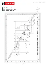
6�4 Electrical circuit connection
Electrical circuit should be connected in accordance with the wire diameters and line numbers specified in the electrical wiring
diagram.
Only electrical professionals are qualified in the operation of electrical installation work.
•
As per the wire diameters and line numbers specified in the electrical schematic diagram, connect the electrical circuit.
• Make sure the power switch is off and hang the warning sign “DON’T TURN ON THE POWER”.
• For 380 V, wire the 4 × 2.5 mm² cable of the control box to the power input terminals.
• For 220 V, wire the 3 × 2.5 mm² cable to the power input terminals.
• Connect bicolour ground wire to the grounding bolt.
• Circuit connection for safety electromagnet: Safety electromagnets mounted on the column, wires from the slot through 4
connections in electric magnet in parallel connected to the control box terminal.
• Circuit connection for limit switch: The limit switches are installed the top of the main column, wires from the slots on the
cross on the control box terminal.
• Decreased solenoid valve coil connection: Decreased power unit solenoid valve coil wires from the column slot through
terminals in the control box.
7 Commissioning
7�1 Fill hydraulic oil
After the hydraulic and electric circuits have been connected as instructed, operate as per the below
steps:
• Fill 12 l wear-resistant hydraulic oil N32 or N46 (supplied by the user) into the oil tank.
Before filling, ensure the hydraulic oil is clean, in order to prevent any impurities from entering
the oil-way and causing it unsmooth�
7�2 Commissioning
Check phase sequence:
Turn on the power switch on the control box and the power indicator lights. Press the UP button to see if the lifting slipways go
up or not. If not up, cut off the power and adjust the power phase sequence to enable the oil pump to supply oil normally. Then
check if the joints between the oil pipe and the oil cylinder leaks oil or not. If yes, check if the joints loosen or not.
After the power is turned on, there is a possibility of high voltage electric shock in the control
box. Thus this operation should be engaged by authorized professionals with qualifications and
experience in electric operation, to avoid the risk of electric shock�
No-load test:
• Press the UP button SB1, and observe if the main and auxiliary carriages are in the same height or not, while the lift
carriages and arms are rising. At the same time, listen to the safety block‘s sound and judge the position of slipways is
high or low. Readjust the steel cable correctly to make the safety blocks’ position in the same height. That is, the main and
auxiliary slipways are in the same height.
•
Press the DOWN button SB2. The oil pump works, the carriages rise first, the time relay is electrified, the mechanical lock
and the drop solenoid valve open in 2-3 seconds, and the hydraulic oil inside the oil cylinder is pressed back to the oil
tank by the weight of working table. Then the decline completed.
•
Press the LOCK button SB3. The drop solenoid valve is electrified, and the mechanical lock is not energized. Then the
slipways decline and the mechanical lock reset under the mechanical spring force to lock the slipways. The Locking
completed and next operation can start safely.
During no-load test, observe if the host lifting is stable or not, the mechanical lock is properly
placed or not, and the oil-way leaks oil or not�
copyrighted
document
- all
rights
reserved
by
FBC

