46
EN
M1.1.HB250CF.NLFREN - 05012018
U
U
S
S
E
E
R
R
’
’
S
S
M
M
A
A
N
N
U
U
A
A
L
L
- 11 -
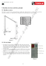
pressure. The oil cylinder drives the lifting arm synchronously with the steel cable and roller wheel and chain.
. W
hen do the vehicle maintenance, operators press the “LOCK” button, the lower solenoid valve works and the
electromagnets do not work when the ca
rriages is locked. When lower the lift, press the “DOWN” button, the time
relay works, the lift raises for 2-3 seconds and lower solenoid valve works at the same time. The weight of vehicle
and lift extrude the hydraulic oil into the oil tank. Finish the lowering operation.
Picture 6
7. Installation
7.1 Installation requirement
-Two post lift must keep install under the safe distance requirement from the wall, column and other equipment.
Minim distance from wall is 800mm, consider the urgency situation and convenience work, the distance of exit
passageway should considered having enough rooms.
Please make sure there is power supply for the control unit.
The indoor height should not be less than 4500mm.
Indoor ground is available for installation, only the ground level meets the installation requirement and have enough
endurance capacity (concrete intensity must be higher than 21MPa, concrete thickness must reach 300mm and
above), otherwise, please pour concrete 1200 * 4000mm in installation space, thickness must reach 300mm and
above.
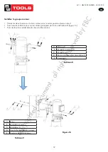
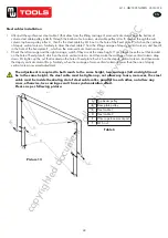
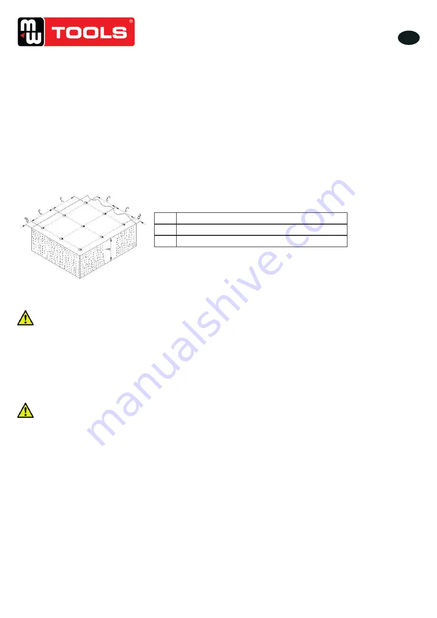
Table 6
Picture 7
A
Concrete thickness must reach 300mm and above
B
Side- hole to the concrete edge must reach 150mm
C
Machine baseboard installation distance
6 Installation
6�1 Installation requirements
• Two post lift must keep install under the safe distance requirement from the wall, column and other equipment.
• Minimum distance from wall is 800 mm, consider the urgency situation and convenience work, the distance of exit
passageway should considered having enough rooms.
• Please make sure there is power supply for the control unit.
• The indoor height should not be less than 4500 mm.
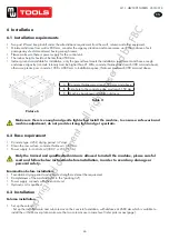
• Indoor ground is available for installation, only the ground level meets the installation requirement and have enough
endurance capacity (concrete intensity must be higher than 21 MPa, concrete thickness must reach 300 mm and above),
otherwise, please pour concrete 1200 x 4000 mm in installation space, thickness must reach 300 mm and above.
A
Concrete thickness must reach 300 mm and above
B
Side-hole to the concrete edge must reach 150 mm
C
Machine baseboard installation distance
Table 4
Picture 6
Make sure there is enough and gentle light when install the machine, to ensure a safe work and
machine adjustment, do not provide strong light and get eyestrain�
6�2 Base requirement
•
Concrete type: 425#, drying period ≥7 days.
•
Clean the raw surface, concrete thickness ≥ 300 mm.
• Power supply for control unit (380 V or 230 V 15 A).
Only the trained and qualified technician is allowed to install the machine, please careful
read and follow below instruction before installation, in order to avoid any damage or
personal safety
�
Examination before installation:
• Foundation drying period and concrete strength must meet the requirement.
• Completeness of the machine (refer to the “packing list”).
• Power supply connects with the control unit.
•
Hydraulic oil is qualified.
6�3 Installation
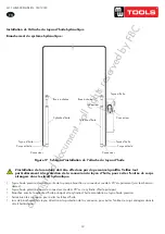
Column installation
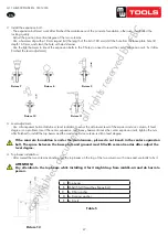
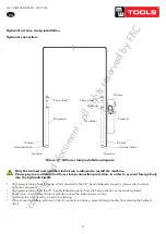
1. Set up the column:
- Set up the installed main and sub columns on the concrete foundation, with distance at 2680 mm which is suitable to
install the oil hose cover plate, make sure the two columns are in same level (refer pictures next page).
copyrighted
document
- all
rights
reserved
by
FBC

