30
FR
M1.1.HB250CF.NLFREN - 05012018
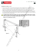
Installation des câbles en acier
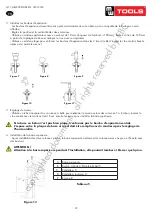
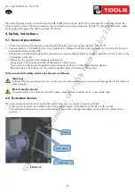
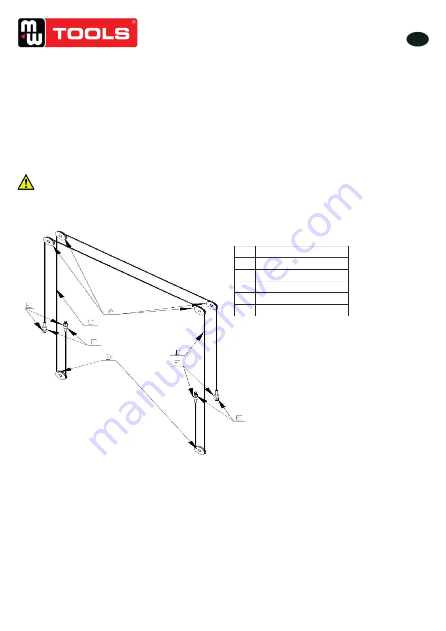
• Après avoir tiré le câble 1 (qui part du chariot de levage de la colonne principale), passez le sous la poulie B de la
colonne secondaire, puis sur la poulie A de la barre supérieure, et fixez le câble avec un écrou M16 dans le trou de la
fixation E sur le chariot de la colonne secondaire. Effectuez la même opération avec le câble 2 qui part du chariot de
levage de la colonne secondaire, et fixez-le dans le trou de la fixation E sur le chariot de la colonne principale.
•
Vérifiez si le chariot de gauche et le chariot de droite sont à la même hauteur. Sinon, desserrez l’écrou de la fixation E de
la colonne principale. Laissez ensuite descendre le chariot de la colonne principale. Ou resserrez l’écrou de la fixation E
de la colonne secondaire et faites remonter le chariot. Procédez de manière inverse si le chariot de la colonne principal est
plus bas que celui de la colonne secondaire.
Le réglage doit être fait de telle manière que les deux chariots (gauche et droit) soient à le même
hauteur, les câbles en acier doivent être bien serrés, placés dans la rainure des poulies, parallèles
entre eux, pour assurer une parfaite synchronisation des chariots�
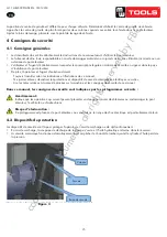
Référez-vous à l’illustration suivante :
U
U
S
S
E
E
R
R
’
’
S
S
M
M
A
A
N
N
U
U
A
A
L
L
- 14 -
Steel cable installation.
-
After pull the synchronous steel cable 1 (that draw from the lifting carriage of main vertical column) pass the bottom
of column steel cable pulley roller B, through the bottom of sub column steel cable pulley roller B,,upward through
the sub column top beam pulley roller A , then fix the steel cable by M16 nut in the hole of the fixed plate
E ,which on the carriage of deputy vertical column. Similarly to draw the steel cable 2 from the lifting carriage of
deputy vertical column , and fixed it in the hole of the fixed plate E , which on the main vertical column carriage.
-Check the left carriage and the right carriage, watch if they are at the same height. If not, please loose the nut that
located on the hole of fixed plate C, which on the main vertical column. And then make the carriage of main vertical
column drop down. Or tighten up the nut that located on the hole of fixed plate C, which on the deputy vertical
column. And then make the deputy vertical column lift up. Similarly, when the carriage of main vertical column is
lower than the one of deputy vertical column, reversed adjustment
The adjustment is required to both reach to the same height, two carriage (left and right) must be in the
same height, the steel cable must be tighten up, not allow any loose, moreover, the steel cable must be
inside the skating slot of steel cable roller, parallel to each other, not allow any cross, otherwise, two
carriages can’t have synchronization effect. Please as per following photo
:
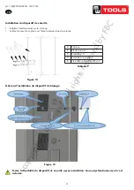
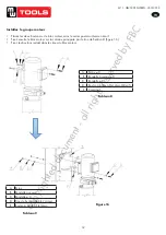
Install the complete insurance device assembly
- Install the insurance electromagnet assembly on the column.
- Insurance block set on the electromagnet assembly on the inside of column.
A Top beam pulley
B Base plate pulley
C Steel cable 1
D Steel cable 2
E Wire rope boom seat post
F M16 nut
Picture 14
Figure 13
A
Poulie barre supérieure
B
Poulie plaque de base
C
Câble en acier 1
D
Câble en acier 2
E
Fixation câble en acier
F
Écrou M16
Tableau 6
copyrighted
document
- all
rights
reserved
by
FBC


