27
FR
M1.1.HB250CF.NLFREN - 05012018
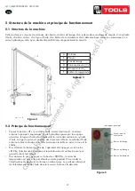
5 Structure de la machine et principe de fonctionnement
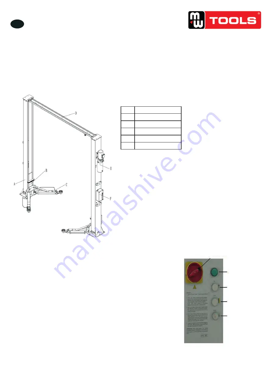
5�1 Structure de la machine
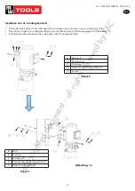
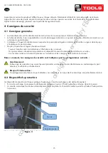
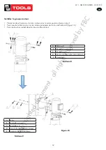
Cette machine se compose de colonnes, de chariots, de bras de levage, d’un système de verrouillage de sécurité, d’un cylindre
d’huile, d’un bloc moteur, d’un tuyau d’huile, d’un boîtier de commande et d’un câble électrique. Un verrou mécanique et un
verrou hydraulique, ainsi qu’un double dispositif de sécurité garantissent la sécurité.
U
U
S
S
E
E
R
R
’
’
S
S
M
M
A
A
N
N
U
U
A
A
L
L
- 10 -
clear of the electrical control panel.
Risks related to appropriate lighting
The operator and the maintenance fitter must be able to assure that all the areas of the lift are properly and
uniformly illuminate compliance with the laws in force in the place of installation.
During up and down operations, the operator should continually observe the lift and can operate it only in the
position of operator. When lifting and lowering the vehicle, the cushion needs being put in the bottom of chassis.
The handling of safety devices is strictly forbidden. Never exceed the maximum carrying capacity of the
lift, make sure the vehicles to be lifted have no load.
6. Machine structure and drive principle
6.1 machine structure
:
-This machine is made of column, carriage, lifting arm, spindle parts, safety lock device, oil cylinder, power unit, oil
hose, control box and electric wire. mechanical lock and hydraulic lock double safety device ensure its security.
Instruction of each part
6.2 Drive principle
:
-
Press button “UP”, the contactor and motor work. Motor drives the gear pump, the hydraulic oil goes through the
one-way valve, oil hose finally reach the in the downward cavity of oil cylinder. The piston rod is pushed by the oil
A
Column
B
Carriage
C
Lifting arm
D
top beam
E
Power unit
F
Control box
Picture 5
Table 5
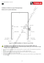
A
Colonne
B
Chariot
C
Bras de levage
D
Barre supérieure
E
Groupe moteur
F
Boîtier de commande
Figure 4
Tableau 3
5�2 Principe de fonctionnement
• Pressez le bouton «UP», le contacteur et le moteur fonctionnent. Le moteur
entraîne la pompe à engrenages, l’huile hydraulique passe par la soupape
anti-retour, le tuyau d’huile atteint finalement la cavité descendante du cylindre
d’huile. La tige du piston est poussée par la pression d’huile. Le cylindre d’huile
entraîne le bras de levage en synchronisme avec le câble en acier, la roue et la
chaîne.
• Pour effectuer l’entretien du véhicule, l’opérateur doit appuyer sur le bouton
«LOCK», l’électrovanne fonctionne et les électro-aimants ne fonctionnent pas
quand le chariot est bloqué.
• Pour abaisser le pont, appuyez sur le bouton «DOWN», le relais de
temporisation est activé, le pont élévateur monte pendant 2-3 secondes et
l’électrovanne de descente fonctionne en même temps. Le poids du véhicule et
de l’élévateur presse de l’huile dans le réservoir. Terminez la descente.
U
U
S
S
E
E
R
R
’
’
S
S
M
M
A
A
N
N
U
U
A
A
L
L
- 11 -
pressure. The oil cylinder drives the lifting arm synchronously with the steel cable and roller wheel and chain.
. W
hen do the vehicle maintenance, operators press the “LOCK” button, the lower solenoid valve works and the
electromagnets do not work when the ca
rriages is locked. When lower the lift, press the “DOWN” button, the time
relay works, the lift raises for 2-3 seconds and lower solenoid valve works at the same time. The weight of vehicle
and lift extrude the hydraulic oil into the oil tank. Finish the lowering operation.
Picture 6
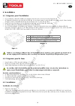
7. Installation
7.1 Installation requirement
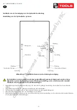
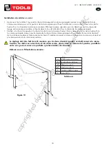
-Two post lift must keep install under the safe distance requirement from the wall, column and other equipment.
Minim distance from wall is 800mm, consider the urgency situation and convenience work, the distance of exit
passageway should considered having enough rooms.
Please make sure there is power supply for the control unit.
The indoor height should not be less than 4500mm.
Indoor ground is available for installation, only the ground level meets the installation requirement and have enough
endurance capacity (concrete intensity must be higher than 21MPa, concrete thickness must reach 300mm and
above), otherwise, please pour concrete 1200 * 4000mm in installation space, thickness must reach 300mm and
above.
Table 6
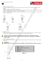
Picture 7
A
Concrete thickness must reach 300mm and above
B
Side- hole to the concrete edge must reach 150mm
C
Machine baseboard installation distance
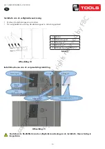
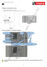
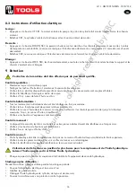
Interrupteur principal
Voyant de mise
sous tension
Bouton de levage
Bouton de blocage
Bouton de descente
Figure 5
copyrighted
document
- all
rights
reserved
by
FBC

