background image

VJ-2638/1638/1638W OPERATION MANUAL

Panel setup menu

5.1  Setup menu

187

NOTE

• When the Spitting menu is set to "On Media", the maximum printable media width becomes 16mm 

shorter.
Therefore, the side margins become the value that you have set in Side Margin menu +8mm.

5.1.2 Spitting menu

• The right side margin will be the following sum depending on the setting.

Y of Origin menu + 8mm (when the spitting is set to On Media) + Value set in Side Margin menu.

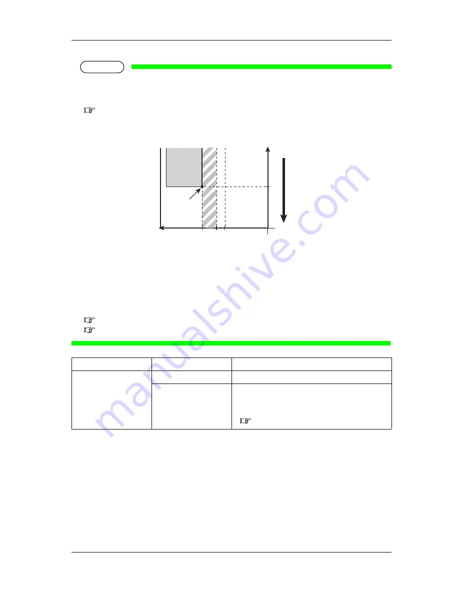
1. Print starting position
2. Media feed direction

X (media feeding distance)
Y (print head transferring distance)
a (0mm/8mm: Spitting setting is ON, Off/On Media)
b (5mm to 25mm: Side margin setting)

5.1.2 Spitting menu
5.1.7.1 Cut Pressure menu

Setup item

Setting

Description

Side Margin

<5mm> to 25mm

Set the side margins.

• [Enter] key: saves the setting and shifts to the previous 

menu.

• [Cancel] key: cancels the setting and shifts to the previous 

menu.

5.1 Setup menu

Y

a

b

0

2

X

1

Summary of Contents for VJ-2638

Page 1: ......

Page 2: ......

Page 3: ...ual may cause harmful interference to radio communications Operation of this equipment in a residential area is likely to cause harmful interference in which case the user will be required to correct the interference at his own expense The CE marking is a mandatory European marking for certain product groups to indicate conformity with the essential health and safety requirements set out in Europe...

Page 4: ...rt of this product or publication may be reproduced copied or transmitted in any form or by any means except for personal use without the permission of MUTOH INDUSTRIES LTD The product and the contents of this publication may be changed without prior notification MUTOH INDUSTRIES LTD has made the best efforts to keep this publication free from error but if you find any uncertainties or misprints p...

Page 5: ...manship of the product the seller produced However if the cause of failure is uncertain decide the action after due mutual consultation Details concerning the warranty are written in the warranty certificate included with the product 2 The warranty shall not apply to any direct or indirect loss or compensation for the loss due to the product that has been subject to misuse neglect or improper alte...

Page 6: ...s and directions in this manual 3 Manual Configuration Section Description 1 Safety instructions This chapter explains the installation of this printer warning terms that operators need to know caution items and warning labels on the printer main unit 2 Product overview This chapter explains the features of the printer along with the names and functions of each part 3 Before using This chapter exp...

Page 7: ...nter safely Warning Meaning Used for dangerous situations where death or serious injury may be caused Used for dangerous situations that may cause slight or medium injury or when all or parts of products are damaged It is used for special cautions and for information that needs to be emphasized Indicates useful tips for operating or understanding the printer Indicates prohibited operations Indicat...

Page 8: ...VJ 2638 1638 1638W OPERATION MANUAL 8 ...

Page 9: ...tatus outline 2 13 2 3 1 Status 2 13 2 3 2 Changing printer status 2 13 3 Before using 3 1 Power cord set connection 3 16 3 2 Turning the power ON OFF 3 20 3 2 1 Turning the power ON 3 20 3 2 2 Turning the power OFF 3 21 3 3 Filling ink 3 23 3 3 1 When using 220ml Ink cartridges 3 25 3 3 1 1 For VJ 2638 1638 3 25 3 3 1 2 For VJ 1638W 3 30 3 3 2 When using 440ml Ink cartridges VJ 2638 1638 3 36 3 3...

Page 10: ... 2 3 Custom micro adjustment pattern 3 113 3 6 2 3 1 Adj Pattern ALL 3 113 3 6 2 3 2 Individual Adj pattern 3 118 3 7 Connecting the printer to PC 3 123 3 7 1 System requirements 3 123 3 7 2 Preparing cables 3 123 3 7 3 Connecting a network interface cable 3 124 4 Handling the printer 4 1 Print flow chart 4 126 4 2 Media 4 128 4 2 1 Media type 4 128 4 2 2 Cautions on handling media 4 129 4 2 3 Pre...

Page 11: ...ion 5 179 5 1 1 1 4 Pre heater menu VJ 2638 1638 5 181 5 1 1 1 5 Platen Heater menu VJ 2638 1638 5 182 5 1 1 1 6 Dryer menu VJ 2638 1638 5 183 5 1 1 1 7 Vacuum Fan menu 5 183 5 1 2 Spitting menu 5 184 5 1 2 1 Spitting Pass Count menu 5 185 5 1 3 Side Margin menu 5 186 5 1 4 Media Set menu 5 188 5 1 5 Media Width menu 5 189 5 1 6 Output Mode menu 5 191 5 1 6 1 Ink Dry Time menu 5 191 5 1 7 Method o...

Page 12: ...16 5 7 Display menu 5 217 5 7 1 Language menu 5 217 5 7 2 Temperature menu 5 218 5 7 3 Length menu 5 218 5 7 4 Remain Ink menu 5 218 5 8 Job Status Menu 5 219 6 Maintenance 6 1 Replacing consumable components 6 222 6 1 1 Replacing Ink cartridges 6 222 6 1 2 Replacing Roll Media 6 230 6 1 3 Replacing Flushing box sponges 6 233 6 1 4 Replacing Cutter 6 239 6 2 Cleaning the printer 6 247 6 2 1 Cleani...

Page 13: ...ng 7 279 7 1 4 Printing related troubleshooting 7 282 7 2 Error messages 7 284 7 2 1 Status messages 7 284 7 2 2 Message type error display and remedies 7 285 7 2 3 Error requiring restart 7 289 7 3 The media is jammed 7 290 8 Appendix 8 1 Product specifications 8 294 8 1 1 Printer specifications 8 294 8 2 Interface specification 8 296 8 2 1 Network interface specification 8 296 8 3 Options Supply...

Page 14: ...Table of Contents VJ 2638 1638 1638W OPERATION MANUAL 14 ...

Page 15: ...instructions This chapter explains the installation of this printer warning terms that operators need to know caution items and warning labels on the printer WARNING When installing and operating this printer be sure to follow the directions and warnings in this manual ...

Page 16: ...to three stages Understand the meanings of the following warning terms and follow the contents instructions in this manual Warning Meaning Used for dangerous situations where death or a serious injury may be caused Used for dangerous situations that may a cause slight or medium injury or when all or parts of the products may be damaged Used for special cautions and for information that needs to be...

Page 17: ...uld lead to an electric shock Do not connect an earth wire to the following places Gas pipes There is a possibility of ignition and explosion Earth wire of telephone cables and lightning rods A heavy current might flow whenever lightning strikes Water pipe and faucet The earth might not work if a plastic pipe is connected in the middle of the metal pipe Do not insert or drop metal or flammable obj...

Page 18: ...he power cord set by force Do not route the power cord set near heating appliances Pay attention to the following points when handling the power plug Any mishandling of the power cable could cause a fire Make sure that no foreign substances such as dust are stuck to the power plug Make sure that the power plug is firmly inserted to the edge of the power socket When handling Ink cartridges pay atte...

Page 19: ...anteed Unpacking or moving this printer must be done by the following number of people More than 4 people Installing the dedicated stands on the printer must be done by the following number of people More than 4 people When taking the printer out of the container box make sure to remove the vinyl install Reinforcement for transportation and hold Reinforcement If lifting up the printer with the vin...

Page 20: ...y hot and you could burn yourself Do not touch Media feed slot Platen and Media guide while Heater is working Media feed slot Platen and Media guide become very hot and you could burn yourself Ventilate the workplace Not doing so may cause nausea or a fire hazzard Right after printing Media guide becomes very hot Allow Media guide to cool down before the next operation ...

Page 21: ...ith each label before operating the printer 1 3 1 Handling the warning labels When handling the warning labels be careful with the following points NOTE Check whether all the warning labels can be read If the letters or illustrations on the label are not clear remove the dirt from the label Use cloth water and mild detergent for removing dirt from the warning labels Avoid organic solvents and gaso...

Page 22: ...638W OPERATION MANUAL 22 1 3 Warning labels 1 3 2 Location and type of warning labels Pasting locations of the warning labels are shown in the following figure 1 3 2 1 VJ 2638 1638 Warning labels No Types of warning labels 1 3 1 2 4 4 5 ...

Page 23: ...he heater ޓ temperature setting ޓ Beware of being burned ٟࡅ ߩ ᐲ ቯߦࠃࠅ ࡄ ࡍޔ 㧙 ޔࡦ ࡊޔ ࠗࠟޓ ߃ࡊ ߇ޓ 㜞 ߣߥࠆߚ ޔ Ἣ ࠍߔࠆᕟࠇ߇ ޕߔ ࠅ ޓ ٟNormal cleaning should be done once ޓ a week if the printer is not used for a ޓ long period If the printer is left without cleaning the ޓ ink will be hardened inside the head ޓ nozzle and may cause the head ޓ trouble ٟ㐳ᦼ㑆ࡊ ࡦ ࠍ ߒߥ ႐วߪ ޔ ޓ ㅳߦ ᐲࡁ ࡑ ࠢ ࡦࠣࠍⴕߞߡ ޕ ߐߛߊޓ ࠢ ࡦࠣࠍⴕࠊߕߦ ߔࠆߣ ޔ ࡁ ࡋޓ...

Page 24: ... ޕߔ ࠅޓ ٟPaper guides platen and paper holding ޓ plate will become hot due to the heater ޓ temperature setting ޓ Beware of being burned ٟࡅ ߩ ᐲ ቯߦࠃࠅ ࡄ ࡍޔ 㧙 ޔࡦ ࡊޔ ࠗࠟޓ ߃ࡊ ߇ޓ 㜞 ߣߥࠆߚ ޔ Ἣ ࠍߔࠆᕟࠇ߇ ޕߔ ࠅ ޓ ٟNormal cleaning should be done once ޓ a week if the printer is not used for a ޓ long period If the printer is left without cleaning the ޓ ink will be hardened inside the head ޓ nozzle and may cause the he...

Page 25: ...638W OPERATION MANUAL Safety instructions 1 3 Warning labels 25 3 4 No Types of warning labels ٟSharp Edges ޓ Do not touch steel belt You may be injured ࠬ ࡌ ٟࠬ ࡌ ߪ ߇ ߊውߞߡ ޕ ߐߛߊߢ ߥࠄ ߢߩߔ ޓ ߌ߇ࠍߔࠆᕟࠇ߇ ࠅ ߔ ޕ ᵈ ޓ ᗧ CAUTION ...

Page 26: ...Safety instructions VJ 2638 1638 1638W OPERATION MANUAL 26 1 3 Warning labels ...

Page 27: ...VJ 2638 1638 1638W OPERATION MANUAL Product overview 1 2 Product overview This chapter explains the features of this printer along with the names and functions of each part ...

Page 28: ...chips greatly improving productivity Use of variable dots can also improve color reproduction 4 Multi heaters adopted for VJ 2638 1638 The media heating system developed by Lamiless series has been arranged for solvent ink Pre heater Platen heater and After heater have been installed to improve ink settlement and drying speed of solvent ink on media 5 Effective use of media Equipped with the origi...

Page 29: ... used in this section are those of VJ 1638 No Name Function 1 Media loading lever Used for fixing or releasing the media Lower Lever to fix the media Lower Lever further to fix the media firmly Used to improve the accuracy of media feeding Raise Lever to release the media 2 Operation panel Used to set the operation condition printer display and various functions 2 2 3 Operation panel 11 1 10 2 3 9...

Page 30: ...with Heaters 7 Pressurizing rollers Installed inside of Front cover Press and hold the whole media when printing 8 Media cut groove Installed inside of Front cover Used to cut media straight 9 Maintenance cover Used to prevent the user from touching the inner mechanical section Open close in the following cases When cleaning Cleaning wiper When cleaning circumference of Print head When replacing C...

Page 31: ... dry ink is installed inside VJ 2638 1638 VJ 1638W is not equipped with Heaters 4 AC inlet Used for connecting the power cord set 5 Network interface cable connector Connects a network interface cable 6 Waste fluid valve Open close when discharging the waste fluid from Waste fluid tank It is normally closed 7 Media loading lever Used for fixing or releasing the media Lower Lever to fix the media L...

Page 32: ...g media 3 Ink cartridge slot Insert Ink cartridges 4 Media guide Used to feed the media smoothly when loading or printing on the media Heater Pre heater to dry ink is installed inside VJ 2638 1638 VJ 1638W is not equipped with Heaters 5 AC inlet Used for connecting the power cord set 6 Network interface cable connector Connects a network interface cable 7 Waste fluid valve Open close when discharg...

Page 33: ...to the following for details regarding the operation method of Operation panel When setting the menu from Operation panel 4 3 Menu setups on Operation panel When performing various operations in Operation panel 4 4 Operating from Operation panel 1 Operation keys NOTE Operation keys are assigned with different functions and names depending on the printer status Normal or Setup menu display For deta...

Page 34: ...zed Returns to the previous menu hierarchy Changes made in the setting are discarded Shifts from Setup menu display to Normal 4 key Nozzle Check key Press and hold this key for two seconds or more to perform Nozzle Check printing 5 key Sets Cleaning Mode The lamp of Cleaning Mode that you set lights up in green Shifts the menu in the lower hierarchy Cleaning key When pressed for more than two seco...

Page 35: ...2 Low lamp Green Lamp ON The head height is set to Low When the High lamp is also turned on the head height is set to Mid Lamp OFF The head height is set to High 13 Take Up lamp Green Lamp ON Media ejection mode is set to Take up Lamp OFF Media ejection mode is set to Off or Auto cut 14 Auto Cut lamp Green Lamp ON Media ejection mode is set to Auto cut Lamp OFF Media ejection mode is set to Off or...

Page 36: ...mes of parts and functions TIP When an error requiring a restart fatal malfunction for the printer operation occurs all lamps blink with an alarm 7 2 3 Error requiring restart If the error persists even when the malfunction is fixed contact your local MUTOH dealer ...

Page 37: ...tus is displayed on LCD monitor 5 7 Display menu 5 7 4 Remain Ink menu In the normal operation 2 3 1 Status During printing To display ink or cartridge errors 7 2 2 Message type error display and remedies The indicator and the corresponding Ink color labels are shown below NOTE The ink color labels are attached to the top of the ink cartridge slots No Name 1 LCD display section 2 Ink level indicat...

Page 38: ...o Indicator to display the conditions of ink cartridges 1 Remaining ink amount More than 80 less than 100 2 Remaining ink amount More than 60 less than 80 3 Remaining ink amount More than 40 less than 60 4 Remaining ink amount More than 20 less than 40 5 Remaining ink amount Less than 20 6 Ink Near End 7 Ink End 8 No cartridge ...

Page 39: ...s functions for printing can be performed on Operation panel Display contents in the LCD monitor of Operation panel are as follows 3 Panel display 2 3 2 Changing printer status Follow the procedure below and change the printer status 1 Normal Setup menu display Press the Menu key on Operation panel when the printer is set to Normal Menu 1 Setup is displayed on Operation panel and the display shift...

Page 40: ...al When the printer is at Setup menu display perform either of the following operations to shift Operation panel to the Normal display Press the Cancel or Menu key on Operation panel In the Setup menu leave the keys untouched for three minutes NOTE For details on Status message refer to 7 2 1 Status messages ...

Page 41: ...VJ 2638 1638 1638W OPERATION MANUAL Before using 15 3 Before using This chapter explains necessary steps before using the printer ...

Page 42: ...used Use a power cord set which is equipped with a protective earth and securely connect it to the outlet Do not use a damaged power cord set It could lead to an electric shock or fire CAUTION Pay attention to the following points when handling the power cord set Do not tamper with the power cord set Do not put heavy objects on the power cord set Do not bend twist or pull the power cord set by for...

Page 43: ...n panel is pressed in Press the key once again to turn OFF the power 2 Connect the power cord set to the AC inlet s located on the right side of the printer NOTE The number of AC inlets differs depending on the printer model VJ 2638 3 locations VJ 1638 2 locations VJ 1638W 1 location VJ 2638 No Name 1 AC inlet 2 Power cord set 1 2 2 ...

Page 44: ...he power socket AC 100 V 120 V or AC 220 V 240 V Do not use multiple plugs on the same socket This could generate heat and might cause a fire Be sure to use a dedicated power socket with an earth wire for the power supply and connect it to the earth wire If the earth wire is not connected it may cause an electric shock or fire Do not connect an earth wire to the following places Gas pipes There is...

Page 45: ...of power socket An earth wire with a copper plate which is buried at 650 mm or more in the ground NOTE Contact your local MUTOH dealer if the earth connection is not cannot be established When the printer is ON do not pull out the power cord set from the power socket Whenever the plug is pulled out from the power socket turn OFF the power on Operation panel and allow one minute or more before inse...

Page 46: ...wer ON 1 Press the Power key on Operation panel to turn ON the printer The Power lamp on Operation panel lights up in blue The printer starts the initial operation When the initial operation is complete the printer enters Normal NOTE If there is a problem during the initial operation a message is displayed on Operation panel and the printer may stop operating If operation stops refer to 7 Troubles...

Page 47: ...ration panel is turned off NOTE If the High lamp on Operation panel lights up in green the head height is set to High or Mid Return the head height to Low before turning the power OFF 4 2 5 3 When setting the head height to Low 2 Press the Power key on Operation panel to turn OFF the printer The Power lamp on Operation panel is turned off NOTE If Operation panel is in the following status the powe...

Page 48: ...height to Low All the lamps on Operation panel and the LCD monitor are turned OFF The printer automatically turns the power OFF NOTE If there is a problem during turning OFF operation a message is displayed on Operation panel and the printer may stop operating If operation stops refer to 7 Troubleshooting and deal with the problem After turning OFF the printer wait for ten seconds or longer to tur...

Page 49: ...your eyes or skin If ink gets into your eyes or sticks to your skin immediately wash it off with water Failing to do so might cause irritation or light inflammation of eyes In case of any abnormality consult a physician immediately Do not disassemble Ink cartridges or Ink packs If disassembled ink might come into contact with your eyes or skin Comply strictly with the following during ink filling ...

Page 50: ...to use the dedicated cleaning fluid VJ 2638 1638 product number VJ MSINK3 CL220 VJ MSINK3 CL1000 VJ 1638W product number RJ FGCLS Shake the Ink cartridges or Ink packs lightly before installing Doing so may affect the print quality When the Ink cartridge or Ink pack is moved from a cold place to a warm place leave it for 3 hours or more in the new printing environment before printing Do not insert...

Page 51: ...el name and follow the correct procedure TIP The 220ml cartridges can be inserted horizontally or vertically This section describes the case of horizontal insertion angle only Refer to 3 3 2 When using 440ml Ink cartridges VJ 2638 1638 for the case of vertical insertion 3 3 1 1 For VJ 2638 1638 1 Turn the printer ON The printer starts the initializing operation After the initial operation is compe...

Page 52: ... Operation panel Insert CleaningCart is displayed on Operation panel 3 Take out Cleaning cartridges 8 pieces from the bags 4 Insert Cleaning cartridge into Ink cartridge slot Keep the arrow of Cleaning cartridge facing up and insert it into the printer No Name 1 Cleaning cartridge 2 Arrow 2 1 ...

Page 53: ... cartridges are installed Busy Washing is displayed on Operation panel and the printer starts charging the cleaning fluid When Celaning fluid has been charged Remove Cartridges is displayed on Operation panel 5 Remove all Cleaning cartridges Busy Washing is displayed on Operation panel and the printer starts head cleaning When head cleaning is complete Wash retry No is displayed on Operation panel...

Page 54: ...s K C M Y 2 each on the back of the printer Shake Ink cartridges 2 to 3 times lightly before installing them into Ink cartridge slots Make sure that Ink cartridges are inserted into the correct Slots Match the ink color label with the ink color before inserting Ink pack Keep the arrow of Ink cartridge facing up and insert it into the printer No Name 1 Ink cartridge 2 Arrow 3 Ink cartridge slots 4 ...

Page 55: ...nk charge is as follows VJ 2638 Approx 20 minutes VJ 1638 Approx 17 minutes When 100 is displayed the initial ink replenishment is complete After the initial ink replenishment is complete Media End is displayed on Operation panel No Name 1 Ink cartridge 2 Ink cartridge slot K1 3 Ink cartridge slot K2 4 Ink cartridge slot C1 5 Ink cartridge slot C2 6 Ink cartridge slot M1 7 Ink cartridge slot M2 8 ...

Page 56: ...lenishment is complete the following results may occur Printed lines become blurred The data is partially not printed In such cases follow 5 3 Cleaning menu and refill a small amount of ink Then check the printing result If there is no improvement in the print result even after refilling a small amount of ink leave the printer unused for an hour or more Then refill a small amount of ink again and ...

Page 57: ... on Operation panel 3 Select whether to perform cleaning of the ink path before the initial ink charge NOTE Cleaning may be required depending on the ink type to be set To perform head cleaning make sure to use the cleaning liquid that matches the ink a When cleaning is required press the key or key to select Yes b When cleaning is not required proceed to the step 8 ...

Page 58: ... Operation panel Insert CleaningCart is displayed on Operation panel 5 Take out Cleaning cartridges 8 pieces from the bags 6 Insert Cleaning cartridge into Ink cartridge slot Keep the arrow of Cleaning cartridge facing up and insert it into the printer No Name 1 Cleaning cartridge 2 Arrow 2 1 ...

Page 59: ... cartridges are installed Busy Washing is displayed on Operation panel and the printer starts charging the cleaning fluid When Celaning fluid has been charged Remove Cartridges is displayed on Operation panel 7 Remove all Cleaning cartridges Busy Washing is displayed on Operation panel and the printer starts head cleaning When head cleaning is complete Wash retry No is displayed on Operation panel...

Page 60: ...s K C M Y 2 each on the back of the printer Shake Ink cartridges 2 to 3 times lightly before installing them into Ink cartridge slots Make sure that Ink cartridges are inserted into the correct Slots Match the ink color label with the ink color before inserting Ink pack Keep the arrow of Ink cartridge facing up and insert it into the printer No Name 1 Ink cartridge 2 Arrow 3 Ink cartridge slots 4 ...

Page 61: ...fter the initial ink replenishment is complete Media End is displayed on Operation panel CAUTION Comply strictly with the following during ink filling If filling is interrupted ink will be lost when filling is resumed Do not turn OFF the power of the printer Do not unplug the power cord set of the printer Do not open Front cover Do not open Maintenance cover Do not raise Media loading lever No Nam...

Page 62: ...n after refilling a small amount of ink leave the printer unused for an hour or more Then refill a small amount of ink again and check the print result If there is still no improvement contact your local MUTOH dealer 3 3 2 When using 440ml Ink cartridges VJ 2638 1638 NOTE 440ml Ink cartridges are not compatible with VJ 1638W Follow the procedure below to install Ink cartridges 1 Check the angle of...

Page 63: ...dge is inserted obliquely the cartridge may fall over 2 Turn the printer ON The printer starts the initializing operation After the initial operation is compete Start Ink Charge E is displayed on Operation panel 3 Press the Enter key on Operation panel Insert CleaningCart is displayed on Operation panel 4 Take out Cleaning cartridges 8 pieces from the bags ...

Page 64: ...leaning cartridge all the way in Ink cartridge slot If the head height is set to High Change Head Gap Low is displayed on Operation panel Change the head height to Low 4 2 5 Head height adjustment When all Cleaning cartridges are installed Busy Washing is displayed on Operation panel and the printer starts charging the cleaning fluid No Name 1 Cleaning cartridge 2 Arrow No Name 1 Cleaning cartridg...

Page 65: ... on Operation panel 6 Remove all Cleaning cartridges Busy Washing is displayed on Operation panel and the printer starts head cleaning When head cleaning is complete Wash retry No is displayed on Oeration panel 7 Press the Enter key on Operation panel Insert InkCartridges is displayed on Operation panel No Name 1 Cleaning cartridge 1 1 ...

Page 66: ...rtridges 2 to 3 times lightly before installing them into Ink cartridge slots Make sure that Ink cartridges are inserted into the correct Slots Match the ink color label with the ink color before inserting Ink pack Keep the arrow of Cleaning cartridge facing the front side of the printer and insert it No Name 1 Ink cartridge 2 Arrow 3 Ink cartridge slots 4 Ink color labels 2 1 3 1 4 3 ...

Page 67: ...filling operation and pause operation are repeated during the initial ink replenishment When 100 is displayed the initial ink replenishment is complete After the initial ink replenishment is complete Media End is displayed on Operation panel No Name 1 Ink cartridge 2 Ink cartridge slot K1 3 Ink cartridge slot K2 4 Ink cartridge slot C1 5 Ink cartridge slot C2 6 Ink cartridge slot M1 7 Ink cartridg...

Page 68: ...TE If the printer perform the nozzle check printing immediately after the initial ink replenishment is complete the following results may occur Printed lines become blurred The data is partially not printed In such cases follow 5 3 Cleaning menu and refill a small amount of ink Then check the printing result If there is no improvement in the print result even after refilling a small amount of ink ...

Page 69: ...nserting Ink cartridges vertically Before installing the 440ml cartridges change the angle as follows 1 Rotale Ink cartridge slot by 90 degrees upward 2 Check if Ink cartridge slot is vertical Check the opposite side in the same way 3 3 3 2 When inserting Ink cartridges horizontally Before installing High capacity ink pack adapters change the angle as follows 1 Tilt Ink cartridge slot slightly tow...

Page 70: ...ink 2 To unlock return Ink cartridge slot to the original position 3 Rotate Ink cartridge slot by 90 degrees downward 4 Check if Ink cartridge slot is horizontal 5 Check the opposite side in the same way No Name 1 Ink cartridge slot No Name 11 Ink cartridge slot 1 1 ...

Page 71: ... VJ 1638W Follow the procedure below to install High capacity ink pack adapter 1 1 Check the angle of Ink cartridge slot to see if the insertion angle of Ink cartridge is horizontal If the insertion angle of Ink cartridge is not horizontal change the angle 3 3 3 Changing the angle of Ink cartridge slot 2 Turn the printer ON The printer starts the initializing operation After the initial operation ...

Page 72: ...s displayed on Operation panel 4 Take out Cleaning fluid pack from the bag 5 Install Cleaning fluid pack and IC chip card to High capacity ink pack adapter NOTE To install or remove High capacity ink pack adapter to from Cleaning fluid pack and IC chip card refer to the operation manual included with High capacity ink pack adapter ...

Page 73: ... not be usable Insert High capacity ink pack adapters all the way in Ink cartridge slots If the head height is set to High Change Head Gap Low is displayed on Operation panel Change the head height to Low 4 2 5 Head height adjustment When all High capacity ink pack adapters are installed Busy Washing is displayed on Operation panel and the printer starts charging Cleaning fluid When Celaning fluid...

Page 74: ...g is complete Wash retry No is displayed on Oeration panel NOTE Do not remove only Cleaning fluid pack while High capacity ink pack adapter is installed on the printer The information of the remaining IC chip card will be rewritten and Cleaning fluid pack will not be usable 8 Press the Enter key on Operation panel Insert InkCartridges is displayed on Operation panel No Name 1 High capacity ink pac...

Page 75: ...C M Y 2 each in Ink cartridge slots K C M Y 2 each on the back of the printer Shake High capacity ink pack adapter 2 to 3 times lightly before installing it in Ink cartridge slot Make sure that Ink packs are inserted into the correct Slots Match the ink color label with the ink color before inserting Ink pack NOTE Do not insert High capacity ink pack adapter into Ink cartridge slot without attachi...

Page 76: ...mplete After the initial ink replenishment is complete Media End is displayed on Operation panel CAUTION Comply strictly with the following during ink filling If filling is interrupted ink will be lost when filling is resumed Do not turn OFF the power of the printer Do not unplug the power cord set of the printer Do not open Front cover Do not open Maintenance cover Do not raise Media loading leve...

Page 77: ... unused for an hour or more Then refill a small amount of ink again and check the print result If there is still no improvement contact your local MUTOH dealer 3 3 5 When using High capacity ink pack adapter for the first time on the printer whose ink is filled If the printer is used without the initial ink replenishment the air inside High capacity ink pack adapter goes into Ink tubes and may cau...

Page 78: ...For types and details of the recommended media contact your local MUTOH dealer 3 4 1 Loading roll media This section describes the procedure to load the roll media Put the roll media in the center of the printer NOTE For VJ 2638 refer to the operation manual of Heavy Duty take up unit Operation Manual for Heavy Duty take up unit 4 3 Setting the Roll Paper The operation manual of Heavy take up unit...

Page 79: ...e roll media 1 Loosen Fixing levers on the Roll media holders both left and right on the back of the printer Set the distance between Roll media holders wider than the actual width of the roll media to be set No Name 1 Roll media holder Left 2 Roll media holder Right 3 Roll media 4 Fixing lever 1 3 4 1 2 2 4 ...

Page 80: ... 3 4 Loading media 2 Tighten Fixing lever of Roll media holder Left and fix the roll media holder Left 3 Set the roll media to Roll media holder Left No Name 1 Roll media holder Left 2 Fixing lever No Name 1 Roll media holder Left 2 Roll media 1 1 2 1 2 ...

Page 81: ...8 1638 1638W OPERATION MANUAL Before using 3 4 Loading media 55 4 Attach Roll media holder Right to the roll media and tighten Fixing lever No Name 1 Roll media holder Right 2 Roll media 3 Fixing lever 1 3 2 ...

Page 82: ...roll media to the center and tighten the levers NOTE When tightening Fixing lever press Roll media holder toward the printer If you do not press Roll media holder Fixing lever may not be completely locked because of the weight of the roll media No Name 1 Roll media holder Left 2 Roll media holder Right 3 Roll media 4 Fixing lever 2 3 3 1 2 1 3 4 4 ...

Page 83: ...ow to set the roll media 1 Turn the printer ON CAUTION Do not operate Media loading lever during initial operation Print head may touch Pressurizing roller and cause a malfunction The printer starts the initializing operation Media End is displayed on Operation panel 2 Raise Media loading lever Lever Up is displayed on Operation panel No Name 1 Media loading lever 1 ...

Page 84: ...NUAL 58 3 4 Loading media 3 Open Front cover 4 Set the roll media to Media feed slot NOTE If the end of the roll media is not wound tightly wind it tightly again and then load it No Name 1 Front cover No Name 1 Roll media 2 Media feed slot 1 1 2 ...

Page 85: ... media holder while holding the edge of the media and eliminate any slack or slant NOTE If you set the roll media free while rewinding the roll media may fall out from Media feed slot and fall toward the back of the printer Confirm that the right edge of the roll media does not go beyond the loading mark If it does it may affect print quality No Name 1 Roll media 2 Media feed slot No Name 1 Roll m...

Page 86: ...hen the media is set as shown in the following figure X follow the procedure to adjust the position of the roll media If the media is set as shown in the following figure X the media may be misaligned or creased during printing For VJ 1638 No Name 1 Roll media 2 Pressurizing rollers No Name 1 Roll media 2 Pressurizing rollers 1 2 1 2 1 5mm 5mm 5mm 1 2 2 2 1 1 ...

Page 87: ...x it with Fixing levers of the right and left Roll media holders NOTE When tightening Fixing lever press Roll media holder toward the printer If you do not press Roll media holder Fixing lever may not be completely locked because of the weight of the roll media No Name 1 Roll media 2 Pressurizing rollers No Name 1 Roll media holder Left 2 Roll media holder Right 3 Roll media 4 Fixing lever 1 2 2 2...

Page 88: ...a loading lever NOTE When loading the new roll media cut the front edge of the media if it is not straight 4 4 3 Cutting media When you increase the pressure for the media lower Media loading lever further as shown below No Name 1 Media loading lever No Name 1 Media loading lever 1 1 ...

Page 89: ... the user type follow 3 4 3 Setting the User Type Setting and set the user type 3 4 3 Setting the User Type Setting This section explains how to set the user type setting Follow the procedure below to set the user type setting 1 Turn ON the printer and load the media After loading the media the printer enters the User Type Setting menu No Name 1 Front cover 1 ...

Page 90: ...Operation panel The user type setting is set Media Initial is displayed on Operation panel and media initialization starts NOTE If the following operations are performed in the User Type Setting menu the printer starts media initial operation without changing the User Type setting Pressing the Cancel key on Operation panel No keys on Operation panel are pressed for ten seconds After media initial ...

Page 91: ...VJ 2638 is not equipped with this function Follow the procedure below to change the torque setting of the Roll media holders 1 Rotate the damper knob placed at the Roll media holder the back left and right of the printer by 90 degrees while pulling it out When you rotate the damper knob by 90 degrees it clicks into place Rotating the damper knob by 90 degrees alternately changes the 1 kg torque an...

Page 92: ...Before using VJ 2638 1638 1638W OPERATION MANUAL 66 3 4 Loading media Torque can be set to either 1kg or 4kg as below No Name 1 Damper knob 1 1 4kg 1kg ...

Page 93: ...the printer works correctly 1 Turn ON the printer and load the roll media 3 4 2 Setting Roll Media 2 Confirm that the printer is in the Normal status 3 Display the Test Print menu on Operation panel a Press the Menu key on Operation panel Menu1 Setup is displayed on Operation panel b Press the key or key on Operation panel to select Menu2 Test Print ...

Page 94: ...anel The display shifts to the Test Print menu 5 2 Test Print Menu 4 Press the key or key on Operation panel to select an item for printing from the following items Nozzle Check Mode Print Setup List Palette Color verify VJ 2638 VJ 1638 only NOTE When the selected print mode of the user type is Graphics 1 or Graphics 2 Palette menu is not displayed ...

Page 95: ... the selected item TIP Refer to the following for details on each of the print list items 3 5 1 Nozzle check to 3 5 3 Setup print 6 Repeat step 4 to step 5 when performing test print for other items 7 Press the Menu key on Operation panel to exit from test print Operation panel returns to Normal The procedure for test printing is complete ...

Page 96: ...whether there are any clogged heads or missing blurred prints NOTE If the nozzle check result shows that the checked points are blurred or missing perform head cleaning 6 2 3 Head cleaning Perform nozzle check once again at the end of the work TIP Refer to the following for printing procedure 3 5 Test print ...

Page 97: ...owing printing conditions PrintMode Effect Pre heater set temperature VJ 2638 1638 Platen heater set temperature VJ 2638 1638 After heater set temperature VJ 2638 1638 Media feed compensation micro adjustment value TIP Refer to the following for printing procedure 3 5 Test print For VJ 2638 1638 For VJ 1638W ...

Page 98: ...N 0WODGT 5GNGEV GPW 㧩 5GVWR WVQ NGCPKPI 9CKVKPI6KOG 㧩 OKP 2TKPVKPI6KOG 㧩 1HH GHQTG 2TKPV 㧩 1HH PM 5VCVWU 5OCTV JKR M E O 4QNN KPF 㧩 1HH ZCWUV CP 㧩 QY QPIUVQTG 4 CKPVGPCPEG PKVKCNK CVKQP KHG 6KOGU GCF ڎڎڎڎڎ GCF ڎڎڎڎڎ 2WOR ڎڎڎڎڎ 2WOR ڎڎڎڎڎ 4 QVQT ڎڎڎڎڎ 2 QVQT ڎڎڎڎڎ 2 FFTGUU 㧩 5WDPGV CUM 㧩 CVGYC 㧩 5NGGR QFG6KOGT 㧩 J CPIWCIG PINKUJ ޓޓޓޓޓޓޓ 6GORGTCVWTG 㧩 GNUKWU 㩩 ޓޓޓޓޓޓޓ GPIVJ 㧩 ޓ OO 7UGT 6 RG 2TKPV QF...

Page 99: ... print 73 3 5 4 Palette print Palette printing is performed as a color demonstration NOTE When the selected print mode of the user type is Graphics 1 or Graphics 2 Palette menu is not displayed TIP Refer to the following for printing procedure 3 5 Test print ...

Page 100: ...become apparent and potentially detrimental to image quality NOTE This function is not shown in VJ 1638W Follow the 2 steps below to check the color reproducibility using the Color Verify 1 Save the baseline Perform the Color Verify under the concition of comparison criterion and save the measured value only one baseline can be saved e g To use a new media after an initial ink charge before starti...

Page 101: ...inting environment for 2 hours before use In this function the baseline cannot be saved for each media To perform the Color Verify with a different media the new baseline should be saved If the media is replace to the one previously used the baseline should be saved again The Color Verify feature is intended to be utilized as an aid to the printer operator in checking for and isolating potential c...

Page 102: ...tion panel menu1 Setup is displayed on the operation panel The operation panel shifts to the Setup menu display b Press the key or key to select menu2 Test Print Press the key on the operation panel c Press the key on the operation panel Test1 Nozzle Check is displayed on the operation panel The display shifts to the Test Print menu 5 2 Test Print Menu ...

Page 103: ...erify 6 Press the Enter key on the operation panel The printing of following items starts a Color Patches b Media Type c Preset Heater Temperature Preset Pre Heater Temperature Preset Platen Heater Temperature Preset Dryer Temperature d Head Temperature Information NOTE Do not open the covers or move media loading lever during printing ...

Page 104: ...d on the operation panel No Name 1 Color Patches 2 Media Type 3 Preset Heater Temperature 4 Head Temperature Information User Type Type 3 Head Temp 1 25 C Head Temp 2 25 C Pre Heater 42 C Praten Heater 42 C Dryer 42 C 0 3 0 3 0 4 0 1 0 2 1 2 1 1 0 6 0 6 0 5 0 1 0 6 0 6 0 2 dE 94 1 0 No discernable difference in color dE 94 3 2 Minimally discernable color difference for colors viewed side by side d...

Page 105: ...e has passed without opening the maintenance cover the print head returns toward the right side of the printer to protect the print head Attaching instrument ENTER is displayed Restart from the Step 8 9 Firmly pinch the tabs on both sides of the connector cap with your fingers pull the connector cap forward to remove it from the print head No Name 1 Maintenance Cover No Name 1 Connector cap 2 Tabs...

Page 106: ...OT installed at an angle and that there is no gap between the connector and spectrophotometer 11 Press the Enter key Wait for a while is displayed on the operation panel The printer checks the connection between the printer and spectrophotometer Set white plate then close left maintenance cover is displayed on the operation panel No Name 1 Spectrophotometer 2 Release buttons 3 Print head section 4...

Page 107: ... original place NOTE Before measuring the color patches make sure that the white side of the white reference plate is facing up If the black side is facing up it will not be measured accurately 13 Close the maintenance cover The print head moves to the right Wait for a while is displayed on the operation panel No Name 1 White reference plate 2 Plate installation place No Name 1 Maintenance cover 1...

Page 108: ...e color patches Measuring is displayed on the operation panel After measuring is complete Detaching instrument ENTER is displayed on the operation panel NOTE Do not open the covers or move media loading lever during measuring 15 Press the Enter key Wait for a while is displayed on the operation panel The print head moves to the left Open left mainte cover is displayed on the operation panel ...

Page 109: ...he printer Detach instrument and Set connector ENTER is displayed on the operation panel 17 While pressing the release buttons on both sides of spectrophotometer pull it forward to remove it from the print head No Name 1 Maintenance Cover No Name 1 Spectrophotometer 2 Release buttons 3 Print head section 1 1 2 1 3 ...

Page 110: ... connector cap with your fingers and install it to the connector at the print head 19 Press the Enter key Wait for a while is displayed on the operation panel Remove white plate then close mainte cover is displayed on the operation panel No Name 1 Connector cap 2 Tabs 3 Print head section 4 Connector 1 2 2 4 1 3 ...

Page 111: ...turn it over so that the black side faces up and install it back to the original place NOTE When the white reference plate is not in use make sure that it is turned over facing down to avoid any contamination 21 Close the maintenance cover No Name 1 White reference plate 2 Plate installation place No Name 1 Maintenance cover 1 1 2 2 3 1 ...

Page 112: ... environment in accordance with the environment condition described in the operating manual 8 1 1 Printer specifications Environment Condition In addition make sure to place the media and ink in the printing environment for 2 hours before use Color Verify is a function to check the color variation in print color caused by various causes This function is not to guarantee the color reproducibility S...

Page 113: ...r key to save the measurement value of the currently printed color patches NOTE When the measurement value is saved the baseline will be replaced by the currently measured value Press Cancel key to not to save the measurement value Ready to Print is displayed on the operation panel ...

Page 114: ...adjust print first 3 6 1 Standard print quality adjustment Adjusts only the print mode in the user type setting which is currently set This menu consists of the following menus Follow the procedure below to perform adjustment 1 Print out the confirmation pattern and check the degree of misalignment 3 6 1 1 Standard confirmation pattern Adjustment method Description Reference Standard Adjusts only ...

Page 115: ...he confirmation pattern again and check if the printer has been adjusted properly 3 6 1 1 Standard confirmation pattern 4 If it has not been adjusted yet return to step 2 NOTE Perform micro adjustment if the printer is not fully adjusted after rough adjustment 3 6 1 1 Standard confirmation pattern Print out the confirmation pattern of the print mode in the user type setting which is currently set ...

Page 116: ...n panel to select Menu1 User Type c Press the Enter key on Operation panel User TypeXX XX is a number between 1 and 15 is displayed on Operation panel d Press the key or key on Operation panel to select the user type setting e Press the Enter key on Operation panel 1 Print Mode is displayed on Operation panel ...

Page 117: ...t quality adjustment 91 f Press the key or key on Operation panel to select Menu2 Adjust Print g Press the key on Operation panel Adjust print1 Standard is displayed on Operation panel h Press the key or key on Operation panel to select Adjust Print1 Standard ...

Page 118: ...ng Up Skip E is displayed on Operation panel This is not displayed for VJ 1638W since it does not perform warming up CAUTION While Warming Up is displayed do not touch Platen and Media guide They become very hot and you could burn yourself NOTE You can start printing during warming up 4 4 7 Starting printing during warming up VJ 2638 1638 A confirmation pattern for print quality adjustment is prin...

Page 119: ...nfirmation pattern printing result is as follows a When the printing result is OK You do not need perform print quality adjustment The procedure for print quality adjustment is complete b When the printing result is NG You need to perform print quality adjustment Perform rough adjustment when the degree of misalignment is big 3 6 1 2 Standard rough adjustment pattern Perform micro adjustment when ...

Page 120: ...s step 2 of 3 6 1 1 Standard confirmation pattern 2 Press the key or key on Operation panel to select Adj 2 Rough Pattern 3 Press the Enter key on Operation panel For VJ 2638 1638 Warming Up Skip E is displayed on Operation panel This is not displayed for VJ 1638W since it does not perform warming up CAUTION While Warming Up is displayed do not touch Platen and Media guide They become very hot and...

Page 121: ...sides and center of the media 4 For Head 1 check the print results on both sides and center of the media and select the number that looks most aligned between 1 and 21 12 is selected in the next printing sample NOTE 11 represents the current setting value 1 2 3 4 5 6 7 8 9 10 11 12 13 14 15 16 17 18 19 20 21 2 1 2 3 4 5 6 7 8 9 10 11 12 13 14 15 16 17 18 19 20 21 1 Pattern for Head 1 Pattern for H...

Page 122: ... and corresponding pattern names are listed as follows NOTE Refer to the following for Print mode 5 1 1 1 1 Print Mode menu 6 Press the key or key on Operation panel to enter the number that you selected in Step 4 NOTE When you press the Cancel key on Operation panel the setting value is not enterd and the display returns to Adj 2 Rough Pattern Print Mode Pattern name Quality 1 2 C Quality 3 4 B G...

Page 123: ...nes the setting Pattern 2 11 is displayed next 8 For Head 2 check the print results on both sides and center of the media and select the number that looks most aligned between 1 and 21 9 Press the key or key on Operation panel to enter the number that you selected in Step 8 1 2 3 4 5 6 7 8 9 10 11 12 13 14 15 16 17 18 19 20 21 2 ...

Page 124: ...n Operation panel 3 6 1 3 Standard micro adjustment pattern Perform micro adjustment when the degree of misalignment is small Print micro adjustment pattern and register the set values 1 Display the Standard Adjust Print menu on Operation panel in the same way as step 2 of 3 6 1 1 Standard confirmation pattern 2 Press the key or key on Operation panel to select Adj 3 Fine Pattern ...

Page 125: ...arming Up is displayed do not touch Platen and Media guide They become very hot and you could burn yourself NOTE You can start printing during warming up 4 4 7 Starting printing during warming up VJ 2638 1638 An micro adjust print pattern is printed for both Head 1 and Head 2 VJ 2638 1638 starts printing after warming up is complete For the micro adjustment pattern the same petterns will be printe...

Page 126: ...he next printing sample NOTE 4 represents the current setting value 5 Pattern 1 4 refer to the chart below for is displayed on Operation panel The pattern name indicated by differs depending on the set print mode Print modes and corresponding pattern names are listed as follows NOTE Refer to the following for Print mode 5 1 1 1 1 Print Mode menu PrintMode Pattern name Quality 1 2 C Quality 3 4 B G...

Page 127: ... you selected in Step 4 NOTE When you press the Cancel key on Operation panel the display returns to Adj 3 Fine Pattern 7 Press the Enter key on Operation panel Determines the setting Pattern 2 4 is displayed next 8 For Head 2 check the print results on both sides and center of the media and select the number that looks most aligned between 1 and 7 ...

Page 128: ...ANUAL 102 3 6 Print quality adjustment 9 Press the key or key on Operation panel to enter the number that you selected in Step 8 10 Press the Enter key on Operation panel Determines the setting Adj 3 Fine Pattern is displayed on Operation panel ...

Page 129: ...een adjusted yet return to Step 2 NOTE Perform micro adjustment if the printer is not fully adjusted after rough adjustment In micro adjustment patterns there are Adjust pattern ALL where all patterns will be adjusted and Individual Adj pattern where the patterns A to F can be adjusted individually 3 6 2 3 1 Adj Pattern ALL 3 6 2 3 2 Individual Adj pattern Menu name Description Reference Custom co...

Page 130: ... degree of misalignment 1 Turn ON the printer and load the roll media 3 4 2 Setting Roll Media 2 Display the Adjust Print menu on Operation panel a Press the Menu key on Operation panel Menu1 Setup is displayed on Operation panel b Press the key on Operation panel to select Menu1 User Type c Press the Enter key on Operation panel User TypeXX XX is a number between 1 and 15 is displayed on Operatio...

Page 131: ... key on Operation panel to select the user type setting e Press the Enter key on Operation panel 1 Print Mode is displayed on Operation panel f Press the key or key on Operation panel to select Menu2 Adjust Print g Press the key on Operation panel Adjust print1 Standard is displayed on Operation panel ...

Page 132: ...3 6 Print quality adjustment h Press the key or key on Operation panel to select Adj Print2 Custom i Press the Enter key on Operation panel Adj 1 Confirm is displayed on Operation panel The display enters the Adjust Print menu 5 1 1 1 2 Adjust Print menu ...

Page 133: ...While Warming Up is displayed do not touch Platen and Media guide They become very hot and you could burn yourself NOTE You can start printing during warming up 4 4 7 Starting printing during warming up VJ 2638 1638 A confirmation pattern for print quality adjustment is printed VJ 2638 1638 starts printing after warming up is complete Six confirmation patterns of A to F will be printed NOTE Becaus...

Page 134: ...tern is printed Operation panel returns to Adj 1 Confirm 4 Confirm that the confirmation pattern printing result is as follows Check each of the confirmation patterns A to F a When the printing result is OK You do not need perform print quality adjustment The procedure for print quality adjustment is complete ...

Page 135: ...tment is required for one of the patterns A to F 3 6 2 3 2 Individual Adj pattern 3 6 2 2 Custom rough adjustment pattern Perform rough adjustment when the degree of misalignment is big Print rough adjustment pattern and register the set values 1 Display the Custom Adjust Print menu on Operation panel in the same way as Step 2 of 3 6 2 1 Custom confirmation pattern 2 Press the key or key on Operat...

Page 136: ...ting VJ 2638 1638 starts printing after warming up is complete For the rough adjustment pattern the same petterns will be printed on both sides and center of the media 6 rough adjustment patterns A to F are printed Enter the adjusted values for both Head 1 and Head 2 1 2 3 4 5 6 7 8 9 10 11 12 13 14 15 16 17 18 19 20 21 1 1 2 3 4 5 6 7 8 9 10 11 12 13 14 15 16 17 18 19 20 21 2 1 2 3 4 5 6 7 8 9 10...

Page 137: ...the following pattern A1 NOTE 11 represents the current setting value 5 Pattern 1 11 refer to the chart below for is displayed on Operation panel 6 Press the key or key on Operation panel to enter the number that you selected in Step 4 NOTE When you press the Cancel key on Operation panel the setting value is not enterd and the display returns to Adj 2 Rough Pattern 1 2 3 4 5 6 7 8 9 10 11 12 13 1...

Page 138: ...1 is displayed next 8 For Head 2 check the print results on both sides and center of the media and select the number that looks most aligned between 1 and 21 9 Press the key or key on Operation panel to enter the number that you selected in Step 8 1 2 3 4 5 6 7 8 9 10 11 12 13 14 15 16 17 18 19 20 21 1 1 2 3 4 5 6 7 8 9 10 11 12 13 14 15 16 17 18 19 20 21 2 ...

Page 139: ...micro adjustment pattern Perform micro adjustment when the degree of misalignment is small This menu consists of the following menus 3 6 2 3 1 Adj Pattern ALL Print micro adjustment pattern ALL and register the set values 1 Display the Custom Adjust Print menu on Operation panel in the same way as Step 2 of 3 6 2 1 Custom confirmation pattern Menu name Description Reference Custom micro adjustment...

Page 140: ... Operation panel For VJ 2638 1638 Warming Up Skip E is displayed on Operation panel This is not displayed for VJ 1638W since it does not perform warming up CAUTION While Warming Up is displayed do not touch Platen and Media guide They become very hot and you could burn yourself NOTE You can start printing during warming up 4 4 7 Starting printing during warming up VJ 2638 1638 ...

Page 141: ... pattern printing 6 adjust print patterns A to F are printed Enter the adjusted values for both Head 1 and Head 2 VJ 2638 1638 starts printing after warming up is complete For the Adjust print pattern the same petterns will be printed repeatedly on both sides and center of the media Pattern for Head 1 Pattern for Head 2 Pattern name ...

Page 142: ...at looks most aligned between 1 and 7 3 is selected in the following pattern A NOTE 4 represents the current setting value 5 Pattern 1 4 refer to the chart below for is displayed on Operation panel 6 Press the key or key on Operation panel to enter the number that you selected in Step 4 NOTE When you press the Cancel key on Operation panel the display returns to Adj 3 Fine Ptn ALL ...

Page 143: ...key on Operation panel Determines the setting Pattern 2 4 is displayed next 8 For Head 2 check the print results on both sides and center of the media and select the number that looks most aligned between 1 and 7 9 Press the key or key on Operation panel to enter the number that you selected in Step 8 ...

Page 144: ...entered press the Enter key to register the set values of patterns A to F Adj 3 Fine Ptn ALL is displayed on Operation panel 3 6 2 3 2 Individual Adj pattern Print one adjustment pattern from A to F and register the set value The following describes how to adjust pattern A only 1 Display the Custom Adjust Print menu on Operation panel in the same way as Step 2 of 3 6 2 1 Custom confirmation patter...

Page 145: ... is displayed do not touch Platen and Media guide They become very hot and you could burn yourself NOTE You can start printing during warming up 4 4 7 Starting printing during warming up VJ 2638 1638 An micro adjust print pattern is printed for both Head 1 and Head 2 VJ 2638 1638 starts printing after warming up is complete For the Adjust print pattern the same petterns will be printed repeatedly ...

Page 146: ... the number that looks most aligned between 1 and 7 6 is selected in the next printing sample NOTE 4 represents the current setting value 5 PatternA1 4 is displayed on Operation panel 6 Press the key or key on Operation panel to enter the number that you selected in Step 4 NOTE When you press the Cancel key on Operation panel the display returns to Adj4 Fine PatternA ...

Page 147: ...key on Operation panel Determines the setting PatternA2 4 is displayed next 8 For Head 2 check the print results on both sides and center of the media and select the number that looks most aligned between 1 and 7 9 Press the key or key on Operation panel to enter the number that you selected in Step 8 ...

Page 148: ...Before using VJ 2638 1638 1638W OPERATION MANUAL 122 3 6 Print quality adjustment 10 Press the Enter key on Operation panel Determines the setting Adj4 Fine PatternA is displayed on Operation panel ...

Page 149: ...commended For the system requirements for the operation of the software server RIP option refer to the operation manual of the software server RIP 3 7 2 Preparing cables The printer is equipped with a network interface for connecting with a PC You need a network interface cable to connect a PC with this printer Prepare the cable depending on the PC that it will be connected to TIP About connecting...

Page 150: ... printer and computer Peer to Peer use a crossover cable 1 Turn OFF both the printer and PC 2 Insert the network interface cable into the network interface connector located on the back of the printer 3 Connect the other connector of the network interface cable to your PC TIP About connecting to your PC refer to the operation manual included with the PC For network setting of the printer refer to ...

Page 151: ...VJ 2638 1638 1638W OPERATION MANUAL Handling the printer 125 4 Handling the printer This chapter explains how to handle the printer ...

Page 152: ...o not spill flammable liquid on Platen It may cause a fire CAUTION Do not touch Media guide while printing Media guide becomes very hot and you could burn yourself Do not touch Media feed slot Platen and Media guide while Heater is working Media feed slot Platen and Media guide become very hot and you could burn yourself Ventilate the workplace Not doing so may cause nausea or a fire hazzard 1 Cre...

Page 153: ...ter 4 1 Print flow chart 127 NOTE Do not open Front cover and Maintenance cover during printing If the above covers are opened printing will be interrupted Printing restarts once Covers are closed However you are not guaranteed to have high print quality ...

Page 154: ...OTE For details of the recommended media contact your local MUTOH dealer If failures or malfunctions of the printer occur by using the media other than the recommended media The printer will not be covered by the warranty and repair expenses will be covered by the customer For details refer to the following 6 Maintenance 7 Troubleshooting To request a repair contact your local MUTOH dealer TIP Whe...

Page 155: ...media may stuck and may not come down In such a case open Front cover after the media is cut and remove the media Do not touch the print side Moisture and oil on your hands may affect the print quality Do not leave media set in the printer for a long time Some media has a tendency to bend causing media jams and degradation of print quality Avoid using such media especially in winter in dry conditi...

Page 156: ...low to change the head height TIP The illustrations used in this section are those of VJ 1638 4 2 5 1 When setting the head height to Mid NOTE Do not open Front cover and change the head height during printing If the head height is changed the alignment will be changed and high print quality will not be guaranteed a c b d Printable Area a 5mm 1 b 5mm to 25mm c 5mm d 5mm to 25mm Media feeding direc...

Page 157: ... 131 1 Open Front cover 2 Change the head height by moving Head height adjustment lever orange High lamp on Operation panel lights up in green Low lamp on Operation panel lights up in green No Name 1 Front cover No Name 1 Head height adjustment lever 1 1 High High Mid ...

Page 158: ...o High NOTE If Head height adjustment lever is raised high print quality is not guaranteed Do not open Front cover and change the head height during printing If the head height is changed the alignment will be changed and high print quality will not be guaranteed 1 Open Front cover No Name 1 Front cover No Name 1 Front cover 1 1 ...

Page 159: ...ving Head height adjustment lever orange NOTE Do not raise Head height adjustment lever higher than the following position Doing so may damage the printer High lamp on Operation panel lights up in green 3 Close Front cover No Name 1 Head height adjustment lever No Name 1 Front cover High High High 1 1 ...

Page 160: ...ge the head height during printing If the head height is changed the alignment will be changed and high print quality will not be guaranteed 1 Open Front cover 2 Change the head height by moving Head height adjustment lever orange Low lamp on Operation panel lights up in green No Name 1 Front cover No Name 1 Head height adjustment lever 1 1 Low Low Low ...

Page 161: ...feeding may be improved with the following methods 1 Adjust the media feed compensation value 4 2 6 1 Procedure for the media feed compensation value 2 Fix the media firmly 4 2 6 2 How to fix the media firmly 4 2 6 1 Procedure for the media feed compensation value 1 Display the Dist Adj menu on Operation panel a Press the Menu key on Operation panel Menu1 Setup is displayed on Operation panel The ...

Page 162: ...u f Press the key or key on Operation panel to select 3 PF Adjust g Press the key on Operation panel PF1 Initial Print is displayed on Operation panel Proceed to Dist Adj menu 5 1 1 1 3 Media feed compensation 2 Performs Initial Adjust Print a Press the Enter key on Operation panel Feed Length 250 mm is displayed on Operation panel TIP The length of media that is fed feeding length for initial adj...

Page 163: ...sure the distance between the two pluses in the initial adjustment print using a ruler 4 Sets up Initial Adjust Change a Press the key or key on Operation panel to select PF2 Initial Change b Press the Enter key on Operation panel Init 250 0 250 mm is displayed on Operation panel c Press the key or key on Operation panel and enter the measured value in Step 3 d Press the Enter key on Operation pan...

Page 164: ...or key on Operation panel and change the set value c Press the Enter key on Operation panel Printing is displayed on Operation panel Starts confirmation adjustment printing When the Confirm Print is complete the printer enters Normal d After the confirmation adjustment printing cut the media 4 4 3 Cutting media 6 Measure the distance between the two pluses in the confirmation adjustment print usin...

Page 165: ...or VJ 2638 1638 Warming up Skip E is displayed on Operation panel This is not displayed for VJ 1638W since it does not perform warming up CAUTION While Warming Up is displayed do not touch Platen and Media guide They become very hot and you could burn yourself NOTE You can start printing during warming up 4 4 7 Starting printing during warming up VJ 2638 1638 Printing is displayed on Operation pan...

Page 166: ...PERATION MANUAL 140 4 2 Media After the micro adjustment printing is completed PF4 Micro Print is displayed on Operation panel 8 Refer to the illustrations below and check the printing result Current adjustment value Input the adjustment value ...

Page 167: ... enter the micro adjustment value according to the printing result in Step 7 The optimal adjusted value has the least white lines or overlapping images Use the number on the bottom right of the printing result as the adjusted value d Press the Enter key on Operation panel The micro adjustment value is saved PF5 Micro Change is displayed on Operation panel 10 Press the Menu key on Operation panel O...

Page 168: ... the edges of the media to curl resulting in damage to the media by the print head surface To prevent this use Media holder plates to reduce the amount of curling in the media Follow the procedure below to install Media holder plates 1 Display the Side Margin menu on Operation panel a Press the Menu key on Operation panel Menu1 Setup is displayed on Operation panel Operation panel shifts to the Se...

Page 169: ...f the Side Margin menu 2 Set up the margins side margins to 10 mm while printing NOTE Set more than 10mm for the side margins In this section the side margins are set to 10mm as a sample a Press the key or key to select Side Margin 10 mm b Press the Enter key on Operation panel After having saved the setting Set3 Side Margin is displayed on Operation panel c Press the Menu key on Operation panel O...

Page 170: ...edia feeding CAUTION If the media jams when using Media holder plates the plates may be deformed When Media holder plates are deformed Do not remove the clogged media by force Stop using the printer Using the printer with deformed Media plates may damage Grid roller or Print heads Contact your local MUTOH dealer NOTE If there is interference with the media as it is fed through the printer after Me...

Page 171: ... OPERATION MANUAL Handling the printer 4 2 Media 145 6 If Media holder plates are not used return the plates to their initial positions as shown in the following figure No Name 1 Roll media 2 Media holder plates 1 2 1 2 ...

Page 172: ...al 2 Press the Menu key on Operation panel Menu1 Setup is displayed on Operation panel 3 Press the key or key on Operation panel to select a setup item and press the key The settings will be confirmed When setup items have a submenu the display shifts to the next menu NOTE When a setup item has a submenu is displayed on the right end of LCD monitor of Operation panel For the general outline of eac...

Page 173: ...n Operation panel to change the setting 5 To save the changed setting press the Enter key on Operation panel The setting is saved and the next setup item is displayed NOTE If you press the Cancel key without pressing the Enter key after changing a setting the changed setting will not be saved 6 Press the Cancel key on Operation panel to exit from the setup Return to the menu in the previous hierar...

Page 174: ...Setup item Description Setup menu Various settings of the printer are configured Test Print menu Performs nozzle check of Print head and setup list Cleaning menu Performs head cleaning Menu Option menu Sets up the contents of the Setup menu Version menu Displays the versions of the firmware Sleep Mode menu Sleep mode settings are configured Display menu Sets the language and unit displayed on LCD ...

Page 175: ... key refer to 2 2 3 Operation panel 4 4 1 Feeding media You can feed the roll media at a position that you want Follow the procedure below to feed media 1 Confirm that Operation panel is Normal 2 Check that Media loading lever is lowered 3 Press the Forward key or the Backward key on Operation panel The media is fed forward or backward 4 Release the Forward key or the Backward key on Operation pan...

Page 176: ...ore than 2 seconds The printer operates as follows NOTE If a large amount of data is saved on the printer Operation panel may not return to Normal by a single Cancel key operation In such cases wait for a few seconds and press the Cancel key again for more than 2 seconds Printer status Operation with the Cancel key pressed for two seconds During printing Terminates the printing and deletes one dat...

Page 177: ...is Normal you can cut the media at the desired position Follow the procedure below to cut the roll media 1 Confirm that Operation panel is Normal 2 Press the Cutting key on Operation panel for more than 2 seconds The printer feeds the roll media to the length of the margin and cuts the media NOTE When loading the new roll media cut the front edge of the media if it is not straight The cutter is a ...

Page 178: ...ht after printing Media guide becomes very hot Allow Media guide to cool down before the next operation Follow the procedure below to cut the roll media 1 Verify the following regarding the operational condition of the printer Printing or other operations are not in progress Operation panel display is Normal 2 To change the position to cut the roll media refer to 4 4 1 Feeding media and advance th...

Page 179: ...ng points when cutting roll media Mishandling Razor blade may cause a cut on your finger or hand When you hold media do not place your finger on Media cut groove Move Razor blade slowly along Media cut groove The procedure for cutting the roll media is complete NOTE When loading the new roll media cut the front edge of the media if it is not straight No Name 1 Media guide 2 Media cut groove 3 Razo...

Page 180: ... procedure below to change or confirm settings for the Panel setup menu 1 Confirm that the printer is in one of the following conditions Receiving data Analyzing data Printing 2 Press the Menu key on Operation panel The following will be displayed on Operation panel VJ 2638 1638 Menu1 Temperature VJ 1638W Menu1 PF Micro Adj 3 Press the key or key to change or confirm settings NOTE For the setting ...

Page 181: ... Reference Temperature VJ 2638 1638 Pre Checks the current temperature of Pre heater Platen Checks the current temperature of Platen heater Dryer Checks the current temperature of Dryer Pre heater VJ 2638 1638 Off 30ºC to 50ºC Changes the temperature of Pre heater 5 1 1 1 4Pre heater menu VJ 2638 1638 Platen heater VJ 2638 1638 Off 30ºC to 50ºC Changes the temperature of Platen heater 5 1 1 1 5 Pl...

Page 182: ...w the procedure below to pause or restart printing NOTE If the printing is paused the print quality will not be guaranteed 1 Check that the printer is in operating 2 Press the Pause key on Operation panel The printer pauses printing PrintRestart ENTER is displayed on Operation panel 3 To restart printing press the Enter key on Operation panel The printer restarts printing ...

Page 183: ...ming up warming up continues until the remperature reaches the set temperature If you start printing during warming up print quality will not be guaranteed 1 Confirm that the printer is warming up Warming Up is displayed on Operation panel 2 Print data will be sent Warming Up and Skip E is displayed on Operation panel CAUTION While Warming Up is displayed do not touch Platen and Media guide You co...

Page 184: ...rrently printing data please refer to the below 4 4 5 2 Settings that can be changed or confirmed while printing To check the information of printed data please refer to the below 5 8 Job Status Menu Follow the procedures below to display the information 1 Check if the printer is printing a data 2 Press key on the operation panel to display Print Remain The remaining length of data currently print...

Page 185: ... Operating from Operation panel 159 3 Press key on the operation panel to display Remain Time The remaining length of data currently printing will be displayed 4 To return the display to Printing press key on the operation panel 㧾㨑㨙㨍㨕㨚 ޓ 㨀㨕㨙㨑 ޓޓ 㨤㨤㨤㨤㨙㨕㨚 㧼㨞㨕㨚㨠㨕㨚㨓 ...

Page 186: ...d NOTE Do not install the printer in a place that is subject to strong light sunlight etc Getting strong light on the color measurement may affect the measurement accuracy To use Spectrophotometer SPECTROVUE VM 10 the printer setting must be as follows Make sure the setting before use Media detection Top Width or Width 5 1 4 Media Set menu Media ejection mode Off or Auto Cut 5 1 6 Output Mode menu...

Page 187: ...and measure the color target NOTE For the setting and operations of the RIP software refer to its operation manual The printer starts printing the color target Printing is displayed on Operation panel After printing is complete Attaching instrument ENTER is displayed on Operation panel NOTE Do not open the covers or move media loading lever during printing 6 Press the Enter key Wait for a while is...

Page 188: ...nel NOTE When a certain time has passed without opening Maintenance cover Print head returns toward the right side of the printer for protection Attaching instrument ENTER is displayed Restart from Step 6 8 Firmly pinch the tabs on both sides of the connector cap with your fingers pull the connector cap forward to remove it from Print head No Name 1 Maintenance cover No Name 1 Connector cap 2 Tabs...

Page 189: ... that Spectrophotometer is NOT installed at an angle and that there in no gap between the connector and Spectrophotometer 10 Press the Enter key Wait for a while is displayed on Operation panel The printer checks the connection between the printer and Spectrophotometer Set white plate then close left maintenance cover is displayed on Operation panel No Name 1 Spectrophotometer 2 Release buttons 3 ...

Page 190: ...d install it back to the original place NOTE Before measuring the color target make sure that the white side of the white reference plate is facing up If the black side is facing up it will not be measured accurately 12 Close Maintenance cover Print head moves to the right Wait for a while is displayed on Operation panel No Name 1 White reference plate 2 Plate installation place No Name 1 Maintena...

Page 191: ...ument ENTER is displayed on Operation panel NOTE Color measurement starts either automatically or manually depending on the RIP software feature The steps above are for manual measurement When the measurement starts automatically Ink Drying xxxxxs xxxxx is a number may be displayed on Operation panel Do not open the covers or move media loading lever during measuring 14 Press the Enter key Wait fo...

Page 192: ... on the left of the printer Detach instrument and set connector cap ENTER is displayed on Operation panel 16 While pressing the release buttons on both sides of Spectrophotometer pull it forward to remove it from Print head No Name 1 Maintenance cover No Name 1 Spectrophotometer 2 Release buttons 3 Print head section 1 1 2 1 3 ...

Page 193: ... on both sides of Connector cap with your fingers and install it to the connector of Print head 18 Press the Enter key Wait for a while is displayed on Operation panel Remove white plate then close left maintenance cover is displayed on Operation panel No Name 1 Connector cap 2 Tabs 3 Print head section 4 Connector 1 2 2 4 1 3 ...

Page 194: ...es up and install it back to the original place NOTE When White reference plate is not in use make sure that it is turned over facing down to avoid any contamination 20 Close Maintenance cover Ready to Print is displayed on Operation panel For the subsequent operations follow the instructions of the RIP software No Name 1 White reference plate 2 Plate installation place No Name 1 Maintenance cover...

Page 195: ... of Print head and setup list 5 2 Test Print Menu Cleaning menu Performs head cleaning 5 3 Cleaning menu Menu Option menu Sets up the contents of the Setup menu 5 4 Menu Option menu Version menu Displays the versions of the firmware 5 5 Version menu Sleep Mode menu Sleep mode settings are configured 5 6 Sleep Mode menu Display Sets the language and unit displayed on LCD monitor of Operation panel ...

Page 196: ... during media initialization Enter key shifts to the sub menu 5 1 5 Media Width menu Output mode Sets the media ejection method after printing Enter key shifts to the sub menu 5 1 6 Output Mode menu Method of Cut Sets the media cutting method after printing Enter key shifts to the sub menu 5 1 7 Method of Cut menu Origin Sets the beginning of printing origin of the print data Enter key shifts to t...

Page 197: ...t Fan menu Longstore Wash Print head with the cleaning fluid Enter key shifts to the sub menu 5 1 19 Longstore menu CR Maintenance Performs maintenance Enter key shifts to the sub menu 5 1 20 CR Maintenance menu Initialization Returns the settings of the printer to default Enter key shifts to the sub menu 5 1 21 Initialization menu Life Times Displays the operational life time of each part Enter k...

Page 198: ... other than recommended one will not be covered by the warranty and repair expenses will be paid by the customer For details contact your local MUTOH dealer Temporary Displays the settings of Off or ALL Off in the Selection menu in the Setup menu temporarily Enter key returns to the previous menu with all set up items displayed Cancel key returns to the previous status in the Selection menu when t...

Page 199: ...ub menu 5 1 1 1 3 Media feed compensation Pre heater Sets the temperature of Pre heater NOTE This function is not displayed for VJ 1638W Enter key shifts to the sub menu 5 1 1 1 4 Pre heater menu VJ 2638 1638 Platen heater Sets the temperature of Platen heater NOTE This function is not displayed for VJ 1638W Enter key shifts to the sub menu 5 1 1 1 5 Platen Heater menu VJ 2638 1638 Dryer Sets the ...

Page 200: ... 4 When the selected print mode of the user type is Graphics 1 or Graphics 2 Palette menu is not displayed 3 5 4 Palette print Setup item Setting Description Mode Quality 1 Sets up print mode Quality 1 to 4 Suitable for printing photos Sets up to perform high quality printing Graphics 1 to 2 Suitable for printing photos Sets up to perform standard printing Banner 1 to 4 Suitable for outdoor signs ...

Page 201: ...inting the selected effect affects the printing speed Effect menu Print Mode Resolution Pass Direction Quality 1 1440x 1440dpi 16 times Uni Uni Direction Quality 2 1440x 1440dpi 16 times Bi Bi Direction Quality 3 720 x 1440dpi 8 times Uni Uni Direction Quality 4 720 x 1440dpi 8 times Bi Bi Direction Graphics 1 720 x 1080dpi 6 times Uni Uni Direction Graphics 2 720 x 1080dpi 6 times Bi Bi Direction...

Page 202: ...nts at a slower speed than Fine Fuzz A S Fine Wave Performs Wave printing using the left side of the of Print head Since only half of Print head nozzles are used printing speed becomes a half of Wave Set up this menu to improve the print quality compared with Fine Fuzz If used when one side of the nozzles are clogged quality deterioration may be avoided B S Fine Wave Performs Wave printing using t...

Page 203: ... print first Standard Adjust Print menu Adjusts only the print mode in the user type setting which is currently set Setup item Setting Description Adjust Print Standard Adjusts only the print mode in the user type setting which is currently set Standard Adjust Print menu Custom Perform adjustment for all print modes Custom Adjust Print menu Cancel key shifts to the previous menu 5 1 1 1 User Type ...

Page 204: ...tern Perform this when the degree of misalignment is big Print Adjust patterns A to F and enter the set values 3 6 2 2 Custom rough adjustment pattern Adj PatternALL Perform this when the degree of misalignment is small Print Adjust patterns A to F and enter the set values 3 6 2 3 1 Adj Pattern ALL Adj PatternA When the degree of misalign is small print out one of the Adjust patterns and enter the...

Page 205: ...he sub menu 3 Confirm Print menu Micro Adj Print Performs Micro Adjustment Print Enter key shifts to the sub menu 4 Micro Adj Print menu Micro Adj Change Sets up Micro Adjustment Change Enter key shifts to the sub menu 5 Micro Change menu Cancel key shifts to the previous menu 5 1 1 1 User Type advanced setup menu Setup item Setting Description FeedLength 100mm to 250mm to 500mm Changes the length...

Page 206: ...e previous menu Cancel key cancels the setting and shifts to the previous menu 5 1 1 1 3 Media feed compensation Setup item Setting Description FeedLength 100mm to 250mm to 500mm Changes the length feed length of the media feed direction for Confirm Print Enter key Determines the setting Printing is displayed on Operation panel and initial adjust print starts After printing the printer enters Norm...

Page 207: ...e heater differs depending on the media Setup item Setting Description Micro Adj Change 5 00 to 0 00 to 5 00 Sets up Micro Adjustment Change Enter key saves the setting and shifts to the previous menu Cancel key cancels the setting and shifts to the previous menu 5 1 Setup menu Setup item Setting Description Pre heater Off 30ºC to 50ºC Sets the temperature of Pre heater 1 Roll media 2 Pre heater 3...

Page 208: ...TE This function is not displayed for VJ 1638W The set temperature of Platen heater differs depending on the media Setup item Setting Description Platen heater Off 30ºC to 50ºC Sets the temperature of Platen heater 1 Roll media 2 Platen heater 3 Print head Enter key saves the setting and shifts to the previous menu Cancel key cancels the setting and shifts to the previous menu 5 1 1 1 User Type ad...

Page 209: ...2 Dryer 3 Print head Enter key saves the setting and shifts to the previous menu Cancel key cancels the setting and shifts to the previous menu 5 1 1 1 User Type advanced setup menu Setup item Setting Description Vacuum Fan Low Set this if there is a possibility of paper jamming from media feed failure when the setting is Middle Middle Set this if there is a possibility of paper jamming from media...

Page 210: ...printable media width becomes 16mm shorter Therefore the side margins become the value that you have set in Side Margin menu 8mm The right side margin will be the following sum depending on the setting Y of Origin menu 8mm when the spitting is set to On Media Value set in Side Margin menu 1 Print starting position 2 Media feed direction X media feeding distance Y print head transferring distance a...

Page 211: ...ocated on the origin side for every shuttle Enter key saves the setting and shifts to the sub menu 5 1 2 1 Spitting Pass Count menu On Media Perform the spitting operation on the page margins The printing speed will be improved since the number of time to return to Spitting box is reduced Enter key saves the setting and shifts to the sub menu 5 1 2 1 Spitting Pass Count menu Off Spitting operation...

Page 212: ...e origin side every five times Print head returns to the origin position Spitting operation is not performed over the media On Media 1 time Performs the spitting operation on Spitting box on the origin side every time Print head returns to the origin position Perform the spitting operation on Spitting box every time Print head returns to the origin position On Media 5 times Performs the spitting o...

Page 213: ...g Y of Origin menu 8mm when the spitting is set to On Media Value set in Side Margin menu 1 Print starting position 2 Media feed direction X media feeding distance Y print head transferring distance a 0mm 8mm Spitting setting is ON Off On Media b 5mm to 25mm Side margin setting 5 1 2 Spitting menu 5 1 7 1 Cut Pressure menu Setup item Setting Description Side Margin 5mm to 25mm Set the side margins...

Page 214: ... Media Width menu 5 1 5 Media Width menu When the the media detection is set to Off the media cannot be cut automatically Setup item Setting Description Init Off The media will not be detected Top Width Detect the media width and edge while initializing the media Width Detect the media width while initializing the media Enter key saves the setting and shifts to the previous menu Cancel key cancels...

Page 215: ...n is performed during media initialization 2 Media Width display menu For media detection settings refer to the following 5 1 4 Media Set menu NOTE When the media is loaded as shown in the illustration and not using media detection the printer may print on between the right edge of Platen and center of the media If this happens adjust the print starting position in Origin menu 5 1 7 1 Cut Pressure...

Page 216: ...dth display menu Setup item Setting Description MediaWidth 210mm to 1000mm to 1 625mm Set the media width Enter key saves the setting and shifts to the previous menu Cancel key cancels the setting and shifts to the previous menu 5 1 1 1 User Type advanced setup menu Setup item Setting Description MediaWidth mm Display the media width that is detected while initializing Cancel key shifts to the pre...

Page 217: ...scription Output mode Off Set when not cutting the media automatically after printing Set it to Off even when cutting the media manually Take up Set when using the take up unit The media will not be cut after printing Auto cut Set when cutting the media automatically 5 1 7 Method of Cut menu Enter key saves the setting and shifts to the sub menu 5 1 6 1 Ink Dry Time menu Cancel key cancels the set...

Page 218: ...gleCut 2 steps Cuts at a shorter process than SingleCut 3 steps method Suitable for media with a narrow width SingleCut 3 steps Normal cutting method DoubleCut 2 steps Set when the media is not cut with SingleCut 2 steps method Suitable for media with a narrow width DoubleCut 3 steps Set when the media is not cut with SingleCut 3 steps method Enter key saves the setting and shifts to the next menu...

Page 219: ...hen reprinting on the margin with changing the printing data position to the printed media NOTE When Output Mode menu is set to Take up the set value X media feeding distance becomes 0 mm to 15000 mm 5 1 6 Output Mode menu Depending on the set value of the side margin the maximum set value of Y print head transferring distance decreases 5 1 3 Side Margin menu ...

Page 220: ... is ON Off On Media b 5mm to 25mm Side margin setting NOTE The right side margin will be the following sum depending on the setting Y of Origin menu 8mm when the spitting is set to On Media Value set in Side Margin menu 5 1 2 Spitting menu 5 1 3 Side Margin menu Enter key Moving Origin Pos is displayed on Operation panel and Print head moves to the starting position The following content is displa...

Page 221: ...ot displayed for VJ 1638W Setup item Setting Description Prev Stick Off The stick prevent operation is not performed On The stick prevent operation is performed Feed the media back and forth to prevent from sticking Enter key saves the setting and shifts to the previous menu Cancel key cancels the setting and shifts to the previous menu 5 1 Setup menu Setup item Setting Description Standby Heating...

Page 222: ...tem Setting Description CR Movement Data Print head moves the range of the print data width The printing speed will be improved since the moving range of Print head is optimized Machine Print head moves from origin to the maximum printable media width MediaWidth Print head shifts within the media width Enter key saves the setting and shifts to the previous menu Cancel key cancels the setting and s...

Page 223: ...uately before printing 5 1 14 Slant Check menu Sets up slanting detection during media loading Setup item Setting Description Strike Wait 0 0 sec to 0 1 sec to 5 0 sec Sets the overwrite wait time Enter key saves the setting and shifts to the previous menu Cancel key cancels the setting and shifts to the previous menu 5 1 Setup menu Setup item Setting Description Slant Check Off Slant Check is not...

Page 224: ...me Set the value for auto cleaning during printing 5 1 15 2 Printing Mode Auto Cleaning Before printing Set the value for auto cleaning before printing 5 1 15 3 Pre printing Mode Auto Cleaning Enter key saves the setting and shifts to the sub menu Cancel key shifts to the previous menu 5 1 Setup menu Setup item Setting Description WaitingTime Off to 10 mins to 360 mins to 1440 mins Sets the time f...

Page 225: ... Off Auto cleaning is not performed Others Perform the head cleaning selected in the Cleaning menu after the setting time has elapsed 6 2 3 Head cleaning Enter key saves the setting and shifts to the previous menu Cancel key cancels the setting and shifts to the previous menu 5 1 15 Auto Cleaning menu Setup item Setting Description Before Print Off The auto cleaning is not performed On Perform the...

Page 226: ...l Length is not used Enter key saves the setting and shifts to the previous menu 5 1 Setup menu Roll1 Sets up the roll media length The set values of the roll media length can be set as Roll1 to Roll3 Enter key saves the setting and shifts to the sub menu 5 1 17 1 Roll Length menu Roll2 Roll3 Cancel key cancels the setting and shifts to the previous menu 5 1 Setup menu Setup item Setting Descripti...

Page 227: ... VJ MSINK3 CL220 VJ MSINK3 CL1000 VJ 1638W product number RJ FGCLS Setup item Setting Description Exhaust fan Off Turn Off Exhaust fan Low Start Exhaust fan at Low High Start Exhaust fan at High Enter key saves the setting and shifts to the previous menu Cancel key cancels the setting and shifts to the previous menu 5 1 Setup menu Setup item Setting Description Longstore Start Wash Print head with...

Page 228: ...to the left Cleaning wiper rises The following content is displayed on Operation panel End Enter key Cleaning wiper returns to the original position Print head returns to the original position Cancel key shifts to the previous menu without maintenance 5 1 Setup menu Setup item Setting Description Initialization ALL All settings can be returned to factory default User Type The setting of the User T...

Page 229: ...e Times Head 1 Display the operational life of each part The lifetime of each part is indicated by the asterisks Maximum 5 asterisks 100 left As the part deteriorates the number of asterisks decreases one by one 20 The part should be changed when all of the asterisks have disappeared and Change is displayed Contact your local MUTOH dealer to ask for replacing parts Head 2 Pump CR Motor PF Motor Ca...

Page 230: ...s key increases the setting value key decreases the setting value Enter key changes the setting for the next segment Save the set values in the 4th segment and returns to the previous menu Cancel key cancels the setting and shifts to the previous menu 5 1 Setup menu Setup item Setting Description Gateway 0 0 0 0 to 192 168 1 254 to 255 255 255 255 Change the gateway by operating the following keys...

Page 231: ... as a reference material to receive technical supports TIP When a print is executed in connection with computer the setting of RIP software will be printed in the Data Header Setup Item Set Value Description Header Dump Off Only a print data will be printed Damp data will not be printed On After printing of print data the dump data will be printed Dump Only a dump data will be printed but the Numb...

Page 232: ...printing when heated This can be minimized by selecting an appropriate setting as follows Setup Item Set Value Description Single head Off Both Print heads are used for printing Head1 Only left Print head is used for printing Head2 Only right Print head is used for printing Cancel key cancels the setting value and shifts to the previous menu 5 1 Setup menu Setup Item Set Value Description Heater C...

Page 233: ...aper cocklings do not occur Powerful The heater works at full power The temperature increases faster than the EcoMode Select Powerful when the place has a sufficient current capacity and paper cocklings do not occur Eco Fixer It requires the same current capacity as the EcoMode Select Eco Fixer to reduce waiting times before printing and paper cocklings Pow Fixer It requires the same current capac...

Page 234: ... 1638 Dryer temperature VJ 2638 1638 Media feed compensation micro adjustment value 3 5 2 Mode print Setup List Setup list printing is performed Used to check the setup item and the user type 3 5 3 Setup print Palette Palette printing is performed as a color demonstration NOTE When the selected print mode of the user type is Graphics 1 or Graphics 2 Palette menu is not displayed Color Verify VJ 26...

Page 235: ...f ink compare to Normal Used when Print head does not improve by normal head cleaning Enter key Cleaning is displayed on Operation panel and head cleaning starts Progress on the Head cleaning is displayed in on Operation panel Little Charge Refills a small amount of ink Charge a small amount of ink when printing is not stable after ink replenishment 3 3 Filling ink Enter key Ink Refill is displaye...

Page 236: ...J 2638 1638 VJ 1638W User Type Off Off Sets up whether to display the User Type menu On On Spitting Off Off Sets up whether to display the Spitting menu On On Side Margin Off Off Sets up whether to display the Side Margin menu On On Media Initial Off Off Sets up whether to display the Media Initial menu On On MediaWidth Off Off Sets up whether to display the MediaWidth menu On On Output mode Off O...

Page 237: ... Longstore Off Off Sets up whether to display the Longstore menu On On CR Maintenance Off Off Sets up whether to display the CR Maint menu On On Initialization Off Off Sets up whether to display the Initialization menu On On Life Times Off Off Sets up whether to display the Life Times menu On On IP Address Off Off Sets up whether to display the IP Address menu On On Subnet Mask Off Off Sets up whe...

Page 238: ...e Menu Option menu ALL Off No items in the Setup menu are displayed Pressing the Enter key deletes for all items in the Menu Option menu Even if you select ALL Off you can display the items temporarily by selecting Temporary in the Setup menu Cancel key saves the setting and shifts to the previous menu 5 Panel setup menu Setup item Setting Description VJ 2638 1638 VJ 1638W ...

Page 239: ...J 1638W Setup item Setting Description Ver M C Main side Controller side Displays the versions of the firmware of the main side M and controller side C Cancel key shifts to the previous menu 5 Panel setup menu Setup item Setting Description Version Displays the versions of the firmware Cancel key shifts to the previous menu 5 Panel setup menu ...

Page 240: ...off except for Power lamp Automatic head cleaning is performed after the time set in the Timer Setting Menu has elapsed 5 6 1 Timer Setting menu TIP The cleaning mode reflects the settings in Operation panel 6 2 3 Head cleaning Setup item Setting Description Sleep Mode Set Timer Set the auto cleaning interval of this printer for Sleep Mode 5 6 1 Timer Setting menu Start Activate Sleep Mode 5 6 2 S...

Page 241: ...h Waste fluid tank is full Ink cartridge is empty Ink cartridge has been removed An ink cartridge other than genuine Ink cartridges is inserted into Cartridge slot etc When the printer returns to a normal state head cleaning is restarted and Sleep Mode continues 7 2 Error messages If one of the above conditions occurs during head cleaning cleaning is stopped When the printer returns to a normal st...

Page 242: ... Ink cartridge has been removed An ink cartridge other than genuine Ink cartridges is inserted into Cartridge slot etc Activate Sleep Mode again after returning the printer to a normal state 7 2 Error messages If the printer is under one of the conditions above during the Sleep mode the printer will not return to the Normal condition even after pressing the Enter key Return the printer to a normal...

Page 243: ...emperature Sets the unit of temperature display 5 7 2 Temperature menu Length Sets the unit to display the length 5 7 3 Length menu Remain Ink Sets whether to display the ink level indicator 5 7 4 Remain Ink menu Enter key saves the setting and shifts to the selected menu Cancel key cancels the setting and shifts to the previous menu 5 Panel setup menu Setup item Setting Description Language Engli...

Page 244: ...s the setting and shifts to the previous menu 5 7 Display menu Setup item Setting Description Length mm Displays the length in millimeters mm inch Displays the length in inches inch Enter key saves the setting and shifts to the previous menu Cancel key cancels the setting and shifts to the previous menu 5 7 Display menu Setup item Setting Description Remain Ink On Displays the ink level indicator ...

Page 245: ... Settings that can be changed or confirmed while printing 4 4 8 Normal Display while Printing The values displayed in this function are just standard values not guarantee the accuracy If the print data includes no length data all information will be displayed as 0 Setup item Setting Description Job Status JobStatus Displays if the print is completed When the print is completed Completed When the p...

Page 246: ...Panel setup menu VJ 2638 1638 1638W OPERATION MANUAL 220 5 8 Job Status Menu ...

Page 247: ...VJ 2638 1638 1638W OPERATION MANUAL Maintenance 221 6 Maintenance This chapter describes daily maintenance of the printer ...

Page 248: ... Replacement time a When Ink Low is displayed on Operation panel This message is displayed when there is a small amount of ink remaining in Ink cartridge The alarm buzzer sounds To stop the buzzer press the Enter key on Operation panel Replace with the new Ink cartridge b When Ink End is displayed on Operation panel This message is displayed when there is no ink remaining in Ink cartridge The alar...

Page 249: ...ere is no Ink cartridge for replacement at hand leave the empty Ink cartridge inserted in the printer Leaving the printer with Ink cartridge removed may result in clogging of Print head 2 Type Our genuine Ink cartridges and Ink packs that are compatible with the printer are as follows For VJ 2638 1638 Description Model No Ink cartridge K Black 220 ml VJ MSINK3A BK220 Ink cartridge K Black 440ml VJ...

Page 250: ... expenses will be paid by the customer 3 Replacing steps Follow the procedure below to replace Ink cartridges and High capacity ink pack adapters CAUTION Before operation make sure to read the Material Safety Data Sheet MSDS When handling Ink cartridges or Ink packs pay attention so that ink does not come into contact with your eyes or skin If ink gets into your eyes or sticks to your skin immedia...

Page 251: ...ck is moved from a cold place to a warm place leave it for 3 hours or more in the new printing environment before printing Do not refill an ink cartridge or ink pack with ink It may result in abnormal printing Insert or remove Ink cartridge and High capacity ink pack adapter at the time of replacement only Otherwise it may result in incorrect printing 1 Replacing 220ml and 440ml Ink cartridges NOT...

Page 252: ...1 Replacing consumable components 2 Remove Ink cartridge that you want to replace from Slot a For 220ml Ink cartridges b b For 440ml Ink cartridges No Name 1 Ink cartridge 2 Ink cartridge slots No Name 1 Ink cartridge 2 Ink cartridge slots 1 2 2 1 1 1 2 2 ...

Page 253: ... times it cannot be used even though ink remains 4 Shake new Ink cartridge two to three times gently before inserting it into Ink cartridge slot 5 Confirm that Operation panel returns to Normal NOTE If Ink cartridge is replaced during printing printing resumes Ink cartridge replacement is complete 2 Replacing High capacity ink pack adapter option NOTE High capacity ink pack adapters are not compat...

Page 254: ...k pack adapter is installed on the printer The information of the remaining IC chip card will be rewritten and Ink pack will not be usable 3 Take out the new Ink pack from the bag NOTE Open the bag just before attaching Ink pack to High capacity ink pack adapter Leaving Ink pack with the bag open for a long time may result in abnormal printing Do not insert or remove High capacity pack adapter mor...

Page 255: ...k the remaining information will be rewritten and the Ink pack will not be usable Insert High capacity ink pack adapters all the way in Ink cartridge slots 6 Confirm that Operation panel returns to Normal NOTE Printing resumes when High capacity ink pack adapter is replaced during printing High capacity ink pack adapter replacement is complete CAUTION In the following cases make sure to perform th...

Page 256: ...ed in the printer runs out End Of Roll is displayed on Operation panel If media runs out during printing the printer stops printing b When you want to change the media type to use 2 Type TIP For types and details of the roll media refer to 8 3 Options Supply list 3 Replacing steps Follow the procedure below to replace the roll media 1 If the printer is turned ON confirm that operation such as prin...

Page 257: ...s 231 3 Turn Flanges of Roll media holder and take up the roll media 4 Loosen Fixing lever of Right roll media holder and remove the roll media from Roll media holder No Name 1 Roll media holder 2 Roll media No Name 1 Roll media holder Right 2 Fixing lever 3 Roll media 1 1 2 1 1 2 3 ...

Page 258: ...ia from Roll media holder left 6 To load another roll media refer to the following TIP For loading the roll media refer to 3 4 Loading media For storing the roll media not in use refer to 4 2 3 Precaution on storing media The procedure for replacing the roll media is complete No Name 1 Roll media holder Left 2 Fixing lever 3 Roll media 2 1 3 1 3 ...

Page 259: ...tall Flushing box sponges in the printer Flushing box sponges are an essential part to make printing consistent 1 Replacement time Replace Flushing box sponges in the following situations When ink clumps have accumulated on Flushing box sponges beyond Flushing box frame 2 Type TIP For types and details of Flushing box sponge refer to 8 3 Options Supply list No Name 1 Ink clump 2 Flushing box frame...

Page 260: ...s while the printer is turned ON Printing or other operations are not in progress Operation panel display is Normal 2 Display the CR Maintenance menu on Operation panel a Press the Menu key on Operation panel Menu1 Setup is displayed on Operation panel Operation panel shifts to the Setup menu display b Press the key on Operation panel Set1 User Type is displayed on Operation panel ...

Page 261: ...el to select Set 20 CR Maintenance d Press the Enter key on Operation panel CR Mainte Start is displayed on Operation panel The display enters the CR Maintenance menu 5 1 20 CR Maintenance menu 3 Press the Enter key on Operation panel Maintenance starts Print head moves to the left CR Mainte End is displayed on Operation panel ...

Page 262: ... replacement position may result in clogging of Print head 5 Lift Flushing box sponge tab and unhook Then remove Flushing box sponge CAUTION Do not spill waste fluid when replacing Flushing box sponges If waste fluid comes into contact with Grid roller it may damage its surface and affect media feeding No Name 1 Front cover No Name 1 Flushing box sponge tab 2 Flushing boxes 1 ...

Page 263: ... OPERATION MANUAL Maintenance 6 1 Replacing consumable components 237 6 Install the new Flushing box sponge to each Flushing box 7 Close Front cover No Name 1 Flushing box sponges 2 Flushing boxes No Name 1 Front cover 1 ...

Page 264: ...g consumable components 8 Press the Enter key on Operation panel Print head returns to its original position CR Mainte Start is displayed on Operation panel 9 Press the Menu key on Operation panel The printer enters Normal Flushing box sponge replacement is complete ...

Page 265: ...s compatible with the printer is as follows 3 Replacing steps Follow the procedure below to replace Cutter TIP The illustrations used in this section are those of VJ 1638 1 Check the followings while the printer is turned ON Printing or other operations are not in progress Operation panel display is Normal 2 Display the CR Maintenance menu on Operation panel a Press the Menu key on Operation panel...

Page 266: ...key on Operation panel Set1 User Type is displayed on Operation panel c Press the key or key on Operation panel to select Set 20 CR Maintenance d Press the Enter key on Operation panel CR Mainte Start is displayed on Operation panel The display enters the CR Maintenance menu 5 1 20 CR Maintenance menu ...

Page 267: ...ance starts Print head moves to the left of the printer cutter replacement position CR Mainte End is displayed on Operation panel 4 Open Maintenance cover on the left of the printer NOTE Replace Cutter in a short time Leaving Print head at the cutter replacement position may result in clogging of Print head No Name 1 Maintenance cover 1 ...

Page 268: ...lightly turn Cutter holder in the direction as illustrated below NOTE Do not press the tab of Cutter strongly or suddenly let go of it There is a spring in Cutter holder and it may fly out Do not push Cutter all the way in Cutter blade may damage the inside of the printer No Name 1 Tab of Cutter 2 Cutter holder 2 1 ...

Page 269: ... cutter blade edge with a hard substance or drop Cutter Cutter blade may be damaged or chipped NOTE Used Cutter should be put in a plastic bag etc and dispose of it in compliance with local ordinance and instructions of local authorities 7 Install a new Cutter as illustrated NOTE Make sure that the spring in Cutter holder does not fly out while installing No Name 1 Razor blade 1 ...

Page 270: ...Maintenance VJ 2638 1638 1638W OPERATION MANUAL 244 6 1 Replacing consumable components No Name 1 Razor blade 1 ...

Page 271: ...of it There is a spring in Cutter holder and it may fly out Do not push Cutter all the way in Cutter blade may damage the inside of the printer Refer to the illustrations below and install Cutter holder correctly If it is not installed correctly it may cause an error If an error occurs check if Cutter holder is installed correctly 9 Close Maintenance cover No Name 1 Tab of Cutter 2 Cutter holder N...

Page 272: ...lacing consumable components 10 Press the Enter key on Operation panel Print head returns to its original position CR Mainte Start is displayed on Operation panel 11 Press the Menu key on Operation panel The printer enters Normal Cutter replacement is complete ...

Page 273: ...n electric shock or fire Immediately turn OFF the power switch disconnect the power plug from the electric socket and contact your local MUTOH dealer CAUTION Unplug the power cable with the power off before cleaning the outer case and inside of the printer Do not use volatile solvents such as thinner benzene or alcohol These solvents may cause damage to the paint Make sure that no moisture enters ...

Page 274: ...ng the printer 6 2 1 Cleaning the outer case CAUTION Unplug the power cable with the power off before cleaning the outer case of the printer This section describes how to clean the outer case Wipe out dust and dirt attached to the outer case by using a soft cloth ...

Page 275: ...er 249 6 2 2 Cleaning the inside of the printer CAUTION Unplug the power cable with the power off before cleaning the inside of the printer This section describes how to clean the inside of the printer Follow the procedure below 1 Open Front cover No Name 1 Front cover 1 ...

Page 276: ...der and dust attached to Pressurizing rollers using a soft brush NOTE Do not blow paper powder inside the printer using tools such as an air duster It may cause an abnormal noise from the inside of the printer VJ 2638 1638 VJ 1638W No Name 1 Pressurizing rollers No Name 1 Pressurizing rollers 1 1 ...

Page 277: ...nce 6 2 Cleaning the printer 251 3 Apply a damp and tightly squeezed soft cloth to wipe out paper powder and ink attached to Platen and Media guide VJ 2638 1638 VJ 1638W No Name 1 Platen 2 Media guide No Name 1 Platen 2 Media guide 1 2 2 2 1 2 2 ...

Page 278: ...ON MANUAL 252 6 2 Cleaning the printer 4 Apply a damp and tightly squeezed soft cloth to wipe off the dirt of the unpainted silver color area in the center of Grid roller VJ 2638 1638 VJ 1638W No Name 1 Grid roller No Name 1 Grid roller 1 1 ...

Page 279: ...ng Head cleaning Follow the procedure below to perform Head cleaning CAUTION Turn on the printer and then perform Head cleaning NOTE When not using the printer for a long period one week or more perform Head cleaning once a week If not performing Head cleaning Print head is clogged Doing so will preserve print quality 1 Confirm that Operation panel is Normal 2 Check that Media loading lever is low...

Page 280: ...leaning mode The following figures explain the LED lights for each Cleaning mode NOTE Head Cleaning can also be performed from Panel Setup menu 5 3 Cleaning menu Cleaning mode Description Short mode Discharges smaller amount of ink compared to Normal Normal mode Select this mode normally Long mode Discharges larger amount of ink compare to Normal Used when Print head does not improve by normal hea...

Page 281: ... sure to do the following When Change Head Gap Low is displayed on Operation panel set the head height to Low After head cleaning is complete Change Head Gap High is displayed on Operatino panel Set the head height to High After changing the setting printing starts 4 2 5 Head height adjustment If blurs or lacking parts in printed media do not disappear with one time of Head cleaning perform Strong...

Page 282: ... to clean Cleaning wiper CAUTION Turn on the printer and then clean Cleaning wiper NOTE Use Cleaning stick to clean Cleaning wiper For details of Cleaning stick refer to 8 3 Options Supply list 1 Turn on the printer and then check the followings Printing or other operations are not in progress Operation panel display is Normal 2 Display the CR Maintenance menu on Operation panel a Press the Menu k...

Page 283: ...38W OPERATION MANUAL Maintenance 6 2 Cleaning the printer 257 b Press the key on Operation panel Set1 User Type is displayed on Operation panel c Press the key or key on Operation panel to select Set 20 CR Maintenance ...

Page 284: ...key on Operation panel CR Mainte Start is displayed on Operation panel The display enters the CR Maintenance menu 5 1 20 CR Maintenance menu 3 Press the Enter key on Operation panel Maintenance starts Print head moves to the left Cleaning wiper rises CR Mainte End is displayed on Operation panel ...

Page 285: ...leaning Ceaning wiper Do not touch Cleaning wiper and Head cap unit Head cleaning may not be performed correctly because of oil from your hands Make sure to use Cleaning stick to wipe Print head A wet Cleaning stick may cause Print head to clog Do not reuse Cleaning stick The attached dust etc may damage Print head No Name 1 Maintenance cover 1 ...

Page 286: ... and dust on Cleaning wiper a Front side of Cleaning wiper Remove the ink and dust in the horizontal direction b Cleaning wiper back side Remove the ink and dust in the upper direction No Name 1 Cleaning wiper 2 Cleaning stick 3 Head cap unit No Name 1 Cleaning wiper 2 Cleaning stick 3 Head cap unit 1 2 3 3 3 1 3 2 ...

Page 287: ...se the right maintenance cover Close the cover firmly until it is locked 7 Press the Enter key on Operation panel Cleaning wiper returns to the original position Print head returns to its original position CR Mainte Start is displayed on Operation panel No Name 1 Maintenance cover 1 ...

Page 288: ...Maintenance VJ 2638 1638 1638W OPERATION MANUAL 262 6 2 Cleaning the printer 8 Press the Menu key on Operation panel The printer enters Normal Cleaning Cleaning wiper is complete ...

Page 289: ...ning the circumference of Print head read this procedure thoroughly to fully understand it and clean promptly and correctly Print head is not in the capping station during cleaning around Print head Cleaning must be complete before Print head dries This operation should be done within 15 minutes If the operation lasts over 15 minutes follow the steps 8 and 9 and stop the operation perform head cle...

Page 290: ...nu on Operation panel a Press the Menu key on Operation panel Menu1 Setup is displayed on Operation panel Operation panel shifts to the Setup menu display b Press the key on Operation panel Set1 User Type is displayed on Operation panel c Press the key or key on Operation panel to select Set 20 CR Maintenance ...

Page 291: ... the Enter key on Operation panel CR Mainte Start is displayed on Operation panel The display enters the CR Maintenance menu 5 1 20 CR Maintenance menu 3 Press the Enter key on Operation panel Maintenance starts Print head moves to the left CR Mainte End is displayed on Operation panel ...

Page 292: ...nance cover on the left of the printer 5 Move Print head by hand until you can see the circumference of Print head CAUTION Do not push Print head strongly It may cause damage and poor print quality No Name 1 Maintenance cover No Name 1 Print head section 2 Circumference of Print head 1 1 2 2 ...

Page 293: ...lack plastic CAUTION When cleaning around Print head Never touch Print head nozzles Doing so may damage Print head Do not touch the tip of Cleaning stick Print head may be damaged because of oil from your hands Never put water etc on the tip of Cleaning stick Doing so may damage Print head Do not reuse Cleaning stick The attached dust etc may damage Print head No Name 1 Circumference of Print head...

Page 294: ...ter 7 When some foreign substance such as dust or ink clump is attached use Cleaning stick to remove it 8 Close Maintenance cover on the left Close Cover firmly until it is locked No Name 1 Cleaning stick 2 Nozzles Never touch Nozzles No Name 1 Maintenance cover 2 2 1 1 1 1 ...

Page 295: ... printer 269 9 Press the Enter key on Operation panel Print head returns to its original position CR Mainte Start is displayed on Operation panel 10 Press the Menu key on Operation panel The printer enters Normal Cleaning the circumference of Print head is complete ...

Page 296: ...ted to properly dispose of waste fluid from the printer in compliance with Wastes Disposal and Public Cleansing Act and local ordinances Delegate disposal to an industrial waste disposal contractor 1 Ready an empty container such as a supply waste fluid bottle to contain the waste fluid 2 Lay a protective material such as waste media on the floor under Waste fluid tank 3 Open the waste fluid valve...

Page 297: ...71 4 After pouring the waste fluid to the empty container close the waste fluid valve securely 5 Wipe the opening of Waste fluid valve with a cloth etc 6 Dispose of the waste fluid as an industrial waste product Disposal of waste fluids is completed No Name 1 Waste fluid valve 1 ...

Page 298: ... Do not slant the printer prop it against a wall or turn it upside down The ink inside the printer may leak Moreover normal operation after shifting to these positions cannot be guaranteed 1 Preparation before moving When using the dedicated Stands follow the procedure below to move the printer 1 Make sure that the printer is turned OFF 3 2 2 Turning the power OFF 2 Dispose of waste fluid 6 3 Disp...

Page 299: ...ance 6 4 Moving or transporting the printer 273 5 Move the printer NOTE The casters supplied with the dedicated Stand are manufactured for little movement in flat indoor areas not for transporting equipment No Name 1 Adjusters 2 Stands 2 1 1 2 1 ...

Page 300: ...er cord set 3 1 Power cord set connection 3 7 Connecting the printer to PC 4 Perform Nozzle check and then confirm that there is no clogging in Print head 3 5 1 Nozzle check 5 Perform Alignment 3 6 Print quality adjustment 6 4 2 Transporting the printer When transporting the printer make sure to pack it in the same condition as purchased using protective and packing materials to protect the printe...

Page 301: ...t included in any items of this section occurs contact your local MUTOH dealer NOTE If you want to receive product warranty prepare the warranty certificate If the warranty certificate is not presented the repair will not be covered by the warranty even if within the warranty period If you have signed a maintenance service contract prepare that or a similar document ...

Page 302: ...g media 2 Is Maintenance cover open Close Maintenance cover 6 2 4 Cleaning Cleaning wiper 6 2 5 Cleaning the circumference of Print head 3 Are all 8 Ink cartridges fully inserted Fully insert all 8 Ink cartridges 6 1 1 Replacing Ink cartridges No Possible cause Remedy Reference 1 Is Ink cartridge cold and frozen Leave Ink bag at room temperature for at least three hours and perform cleaning severa...

Page 303: ...e Maintenance cover 6 2 4 Cleaning Cleaning wiper 6 2 5 Cleaning the circumference of Print head No Possible cause Remedy Reference 1 Is Front cover open or Media loading lever raised Close Front cover Lower Media loading lever 3 4 Loading media 2 Is Maintenance cover open Close Maintenance cover 6 2 4 Cleaning Cleaning wiper 6 2 5 Cleaning the circumference of Print head 3 Is the media loaded at ...

Page 304: ...omputer side and printer side No Possible cause Remedy Reference 1 Is Network interface cable connected correctly Confirm the types of the cross and straight cables and connect Network interface cable correctly 3 7 3 Connecting a network interface cable 2 Are the network settings configured correctly Configure the network settings correctly 5 1 23 IP Address menu to 5 1 25 Gateway menu 3 Do the pr...

Page 305: ... media loaded correctly Load the roll media correctly 3 4 1 Loading roll media 4 Are there any foreign materials such as torn paper attached to Pressurizing roller Clean Pressurizing roller 6 2 2 Cleaning the inside of the printer 5 Is the printer being used in an environment other than the one specified such as in direct sunlight Only use the printer in an environment that is specified for use In...

Page 306: ...side of the printer 5 Is the printer used in an environment other than the one specified such as near an air conditioner Only use the printer in an environment that is specified for use Installation manual 6 Are you using creased damaged torn or curled media Replace the media 4 2 2 Cautions on handling media No Possible cause Remedy Reference 1 Are you using the recommended media Use the recommend...

Page 307: ...cified environment 4 2 2 Cautions on handling media 3 Are you using the old media Replace it with the new media 6 1 2 Replacing Roll Media 4 Are you using the creased or wrinkled media 5 Does the media bend Use the recommended media When using media other than the recommended one set the Vacuum Fan menu 4 2 1 Media type 5 1 1 1 7 Vacuum Fan menu No Possible cause Remedy Reference 1 Are you using t...

Page 308: ...ct Load the media correctly 3 4 2 Setting Roll Media 2 Did you set up the origin and print position Cancel or reset the settings of the origin and print position 5 1 7 1 Cut Pressure menu No Possible cause Remedy Reference 1 Are you using the recommended media Use the recommended media 4 2 1 Media type 2 Are you using the thick or thin media Use the recommended media 4 2 1 Media type 3 Is the medi...

Page 309: ...the temperature setting of each heater appropriate VJ 2638 1638 Set the temperature appropriately 5 1 1 1 4 Pre heater menu VJ 2638 1638 to 5 1 1 1 6 Dryer menu VJ 2638 1638 7 Is the head height set to High or Mid Return the head height to Low 4 2 5 Head height adjustment No Possible cause Remedy Reference 1 Is Ink cartridge within the validity period Use a new Ink cartridge 6 1 1 Replacing Ink ca...

Page 310: ...g Up Skip Enter Received the printing data while Heater is warming up To start printing before Heater is warmed up press the Enter key VJ 2638 1638 4 4 7 Starting printing during warming up VJ 2638 1638 9 Cleaning Cleaning the head Please wait a while 6 2 3 Head cleaning 10 Ink Refill Filling the ink Please wait a while 3 3 Filling ink 11 SubTank Refill Filling the subtank Please wait a while 3 3 ...

Page 311: ... in the following cases During power shutdown Before head cleaning Set the head height to Low 4 2 5 3 When setting the head height to Low 19 Change Head Gap High Set the head height to High Starts printing 4 2 5 2 When setting the head height to High 20 Insert CleaningCart Washing Print head Install Cleaning cartridge 3 3 Filling ink 21 Insert InkCartridges Filling the ink Insert Ink cartridge 3 3...

Page 312: ...d and Ink cartridge 6 1 1 Replacing Ink cartridges 13 Check Ink Ink cartridges Ink packs cannot be recognized correctly Insert Ink cartridge Ink pack adapter again Contact your local MUTOH dealer 6 1 1 Replacing Ink cartridges 14 S C ReadErr IC chip cannot be read Insert Ink cartridge again If IC chip still cannot be read insert a new Ink cartridge 6 1 1 Replacing Ink cartridges 15 S C Col Err Ink...

Page 313: ... Error Media width The width of the media installed does not match the color target to be measured VJ 2638 1638 Remove the media currently set and set a correct color target 3 4 Loading media 29 Measurement Error Command The parameters of the command sent from RIP software are abnormal VJ 2638 1638 Check the settings of color calibration or color profiling of the RIP software 30 Measurement Error ...

Page 314: ...ctrophotomet er VJ 2638 1638 36 Measurement Error White Calibration White calibration has failed VJ 2638 1638 Open Maintenance cover on the left side of the printer and install White reference plate correctly When White reference plate is contaminated apply a damp and tightly squeezed soft cloth to clean it Start printing and measuring the color target again If you still have trouble contact your ...

Page 315: ...el Pressing any key on Operation panel stops the beeping For an error requiring restart operation will return to normal after removing the cause of the error and restarting the printer If the same error continues to be displayed contact the your local MUTOH dealer Be sure to tell us the code no of the error message when you contact us NOTE in the error message is the code no that indicates what ty...

Page 316: ...inter 3 2 2 Turning the power OFF 2 Open Front cover 3 Move Print head section from the top of the media to the right NOTE When the head height is set to Low change it to High and then shift Head After shifting Head change the setting back to Low 4 2 5 2 When setting the head height to High 4 2 5 3 When setting the head height to Low No Name 1 Front cover No Name 1 Print head section 2 Roll media ...

Page 317: ...AL Troubleshooting 7 3 The media is jammed 291 4 Raise Media loading lever 5 Pull the media to your side and cut the torn part with cutting tools such as a razor blade No Name 1 Media loading lever No Name 1 Razor blade 2 Roll media 1 ...

Page 318: ...638 1638W OPERATION MANUAL 292 7 3 The media is jammed 6 Turn Flanges of Roll media holder and take up the roll media 7 If paper dust or pieces of paper remain inside the printer remove them No Name 1 Flanges 2 Roll media 1 1 2 ...

Page 319: ...VJ 2638 1638 1638W OPERATION MANUAL Appendix 293 8 Appendix This chapter describes specifications and included components with this printer ...

Page 320: ...m when the head height is Mid 2 8 mm when the head height is High Maximum printable media width 1 615 mm 2 632 mm Print margin Top 5 mm 15 mm after media initialization or after winding the media manually 40 mm when media initialization front edge detection is ON or after cutting the media Bottom 5 mm 102 mm at the roll media end Left 5 mm to 25 mm Right 5 mm to 25 mm Media cut system Horizontal a...

Page 321: ...C to 60ºC Humidity 20 to 80 No condensation Storage life six months Archiving condition Ink filled Temperature 10ºC to 40ºC Humidity 20 to 80 No condensation Storage life four days 32ºC or higher Power Power voltage AC 90 V to AC 132 V AC 198 V to AC 264 V Frequency 50 Hz 60 Hz 1 Hz Power consumption Printing 200 W MAIN 1100W HEATER 1250W MAIN 1300W HEATER 2600W Standby 24W 30W 40W Outer diameter ...

Page 322: ...ecifications supported by this printer 8 2 1 Network interface specification Items Specification Network type Ethernet IEEE802 3 Network I F 10BASE T 100BASE TX VJ 1638 1638W Automatic transfer type 10BASE T 100BASE TX 1000BASE T VJ 2638 Automatic transfer type RJ 45 Connector twisted pair cable MDI MDI X Automatic transfer Corresponding protocol TCP IP ...

Page 323: ...VJ 2638 1638 1638W OPERATION MANUAL Appendix 8 3 Options Supply list 297 8 3 Options Supply list For more information about the options and the supply items contact your local MUTOH dealer ...

Page 324: ...Appendix VJ 2638 1638 1638W OPERATION MANUAL 298 8 3 Options Supply list ...

Page 325: ... menu configuration diagram refer to the followings NOTE For details of each setup item refer to followings Setup menu diagram Ready to Print 5 Panel setup menu Setup menu diagram Receiving Converting Printing 4 4 4 Cutting media manually The parts in each list are factory default settings initial values ...

Page 326: ...f Output Mode Method of Cut Origin Prev Stick Standby Heating Head Travel Multi Strike Strike Wait Slant Check To Setup menu diagram Ready to Print 3 4 1 Cnt to 999 Cnt 0 Sec to 60 min Low High To Setup menu diagram Ready to Print 2 4 On On Media Off 10 mm to 25 mm Off Top Width Width 210mm to 1 000 mm to 1 625 mm 210mm to 1 000 mm to 2 642 mm Off Take Up Auto Cut SingleCut 2 steps SingleCut 3 ste...

Page 327: ...cro Change Print Mode Adjust Print PF Adjust Pre Heater Platen Heater Dryer Vacuum Fan None 1 Wave Fine Fuzz Fine Fog 1 A S Fine Wave B S Fine Wave Confirm Pattern Rough Pattern Fine Pattern Confirm Pattern Rough Pattern Fine Pattern ALL Fine Pattern A Fine Pattern B Fine Pattern C Fine Pattern D Fine Pattern E Fine Pattern F 100 mm to 250 mm to 500 mm Initial Print menu setting value 50 0 mm 100 ...

Page 328: ...k Gateway Header Dump Single Head Heater Control Temporary WaitingTime PrintingTime Before Print 1 m to 30 m to 99 m K k C c M m Y y Off Roll 1 Roll 2 Roll 3 Off Low High ALL User Type Setting other than User Type Head1 Head2 Pump CR Motor PF Motor 0 0 0 0 to 192 168 1 253 to 255 255 255 255 0 0 0 0 to 255 255 255 0 to 255 255 255 255 0 0 0 0 to 192 168 1 254 to 255 255 255 255 Off On Dump Off Hea...

Page 329: ...ingle Head Heater Control ALL On ALL Off Ver M Main C Controller Set Timer Start Language Temperature Length Remain Ink JobStatus ToDo Length Done Remain To Setup menu diagram Ready to Print 1 4 Test Print Cleaning Menu Option Version SleepMode Display Job Status Off On Off On Off On Off On Off On Off On Off On Off On Off On Off On Off On Off On Off On Off On Off On Off On Off On Off On Off On Off...

Page 330: ...u diagram Receiving Converting Printing Temperature Pre Heater Platen Heater Dryer PF Micro Adj Backup Pre Heater Platen Heater Dryer Job Status ToDo Length Done Remain Remain Time Off 30 C to 50 C Off 30 C to 50 C Off 30 C to 50 C 5 00 to 0 00 to 5 00 VJ 2638 1638 only ...

Page 331: ...Pressure menu Added a function to select the cutting pressure p 216 02a 03 Change Chapter 5 5 1 26 Header Dump menu Changed the part of the description to the note p 229 02a 03 Change Chapter 5 5 1 28 Heater Control menu Added the heater control function to reduce heat deformation of printing media p 230 p 231 02b 03 Change Chapter 5 5 7 Display menu Added a function to display hide the ink level ...

Page 332: ...ation of step 5 p 280 03 Change Chapter 6 6 2 5 Cleaning the circumference of Print head 3 Correct the step 1 1 Check the followings while the printer is turned ON Correct the illustration and the table of step 6 Correct the illustration and the table of step 7 p 287 p 291 p 292 03 Change Chapter 6 6 3 Disposal of waste fluids Corrected the illustration of open close direction of Waste ink bottle ...

Page 333: ......

Page 334: ......

Reviews: