background image

Mutoh’s DT-Series Printers – Operation Instructions


 26


AP-75171, Rev. 1.1, 25/06/04 


2.3. VERIFICATION OF PACKAGED ITEMS 

After unpacking the packaging box, inspect if the unit is not damaged and that all necessary parts are 
present. 


Notes : 


If any part is missing or broken, contact either of the following: 

o

  The shop where you bought your MUTOH printer. 

o

  Your local MUTOH dealer. 


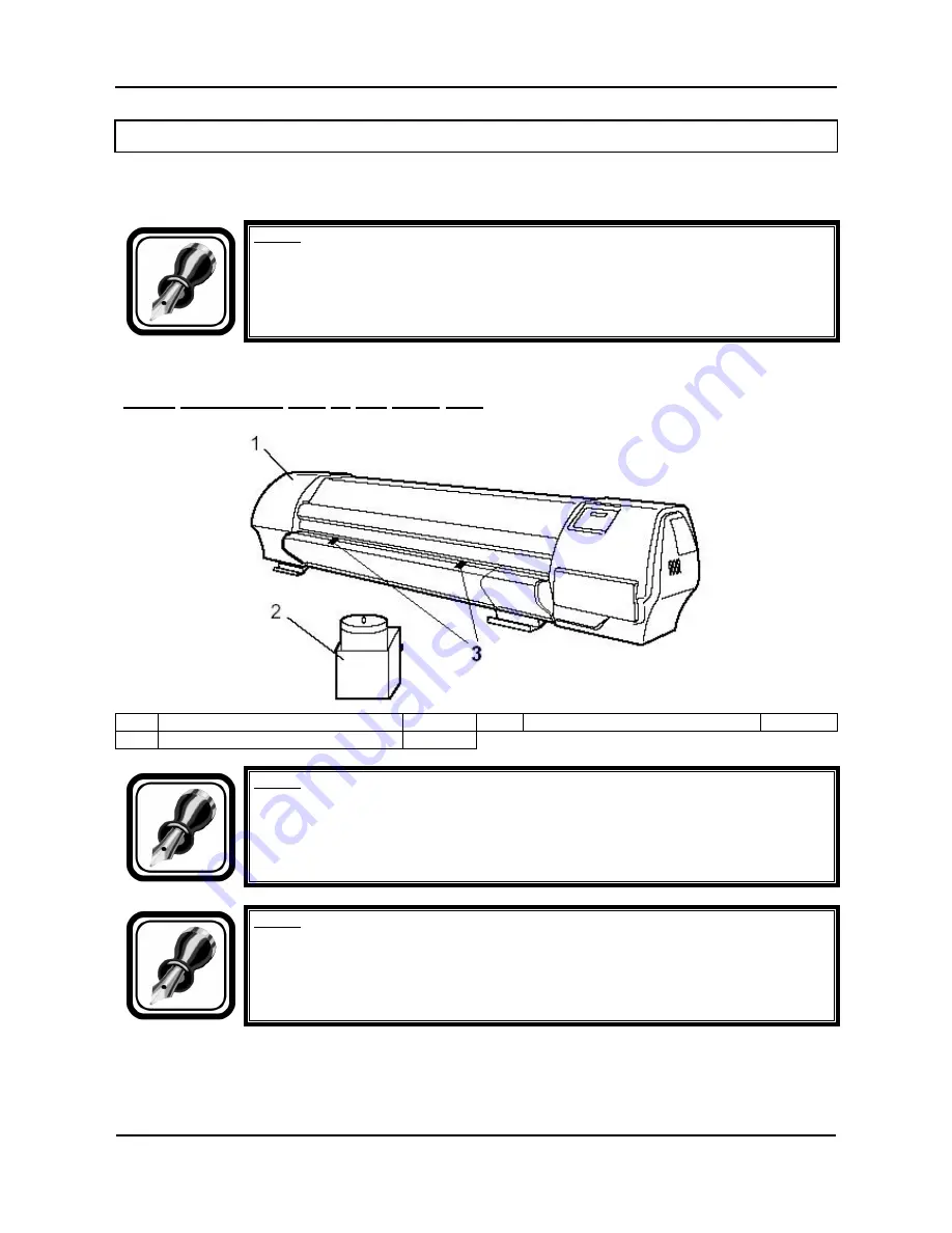
2.3.1. Packaging box of the main unit 


Main unit 

1 set 

Media retainers 

Waste fluid tank 

1 set 


Notes : 
 
The unit is delivered / shipped with special shipping liquid.  This to prevent air coming 
into the ink supply system.  Make sure that air never comes into the ink supply system. 


Notes : 
 
The two media retainers are taped (in bag) onto the print platform. 


Summary of Contents for DT-Series

Page 1: ...Mutoh s Digital Transfer Printer DT Series Printers Operation Instructions MUTOH EUROPE N V AP 75171 Rev 1 1 25 06 2004...

Page 2: ...Mutoh s DT Series Printers Operation Instructions 2 AP 75171 Rev 1 1 25 06 04...

Page 3: ...nformation contained in this document the party to whom it is given assumes its custody and control and agrees to the following The information herein contained is given in confidence and any part the...

Page 4: ...Mutoh s DT Series Printers Operation Instructions 4 AP 75171 Rev 1 1 25 06 04...

Page 5: ...and drop on demand inkjet narrows considerably One application possibility in the field of digital textile printing is heat transfer apparel Mutoh s DT Series Printers are offered in two different mo...

Page 6: ...Mutoh s DT Series Printers Operation Instructions 6 AP 75171 Rev 1 1 25 06 04...

Page 7: ...3 Verification of packaged items 26 2 3 1 Packaging box of the main unit 26 2 3 2 Accessories box 27 2 3 3 Stand packaging box KIT 28 2 3 4 Unwinder Winder 100 Box 28 2 4 Part names and functions 29...

Page 8: ...tenance 71 4 1 Replacing ink cassettes 71 4 2 Replacing the cutting blade 74 4 3 Replacing the waste liquid tank 79 4 4 Cleaning 81 4 4 1 Cleaning the outer case 81 4 4 2 Cleaning the inside of the pr...

Page 9: ...njury moderately or lightly or damage to your equipment Notes Contains important information and useful tips on the operation of your printer 1 3 IMPORTANT SAFETY INSTRUCTIONS General safety instructi...

Page 10: ...low the instructions below when handling the power cable o Do not modify the cable o Do not put heavy objects on the cable o Do not bend twist or pull the cable o Do not wire the cable near equipment...

Page 11: ...touch the cleaning wiper or the head cap unit while cleaning the cleaning wiper Doing so may result in poor head cleaning because of oil on your hands Do not tilt the printer stand it against a wall...

Page 12: ...he ink supply system Make sure that air never comes into the ink supply system 1 4 WARNING LABELS The handling attachment locations and types of warning labels are explained below Warning labels are a...

Page 13: ...Mutoh s DT Series Printers Operation Instructions 13 AP 75171 Rev 1 1 25 06 04 1 4 2 Warning and operation procedure labels on front side No Type 1 2...

Page 14: ...tions 14 AP 75171 Rev 1 1 25 06 04 1 4 3 Warning labels on rear side No Type 3 CAUTION THIS UNIT HAS TWO POWER SUPPLY CORDS WHEN WiNDING UNIT IS PROVIDED TO REDUCE THE RISK OF ELECTRICAL SHOCK DISCONN...

Page 15: ...clamp from waste tubes On right bottom side of machine Remove dummy cassettes before powering on the printer 2 BEFORE powering on printer REMOVE clamps from waste tubes 3 You can also find a label on...

Page 16: ...Media cockling is prevented to avoid the print heads to touch the media protect heads and print result and to avoid the cockling structure to become apparent in the print result 1 5 1 1 Unwinder winde...

Page 17: ...to 50 C Caution We recommend you to set the pre heater temperature at 50 C This to be sure that transfer paper is already expanded a little before reaching the pressure rollers 1 5 1 4 Extra fans The...

Page 18: ...ia is loaded correctly straight Otherwise media can slant and the media retainers could tear the transfer paper 1 5 2 Measurements to minimize head touching cockling media In case of media cockling fo...

Page 19: ...Height The DT series printer can be set at the following head heights 1 2 mm LOW 2 2 mm MIDDLE and 4 mm HIGH Caution We recommend you to use the lowest possible head height This to obtain the best pr...

Page 20: ...Mutoh s DT Series Printers Operation Instructions 20 AP 75171 Rev 1 1 25 06 04...

Page 21: ...printer from ventilating and cause fire Keep the printer away from humid and dusty areas Humidity may result in electrical shock or fire Choose a place for printer installation following the requirem...

Page 22: ...en though the condition is within the range written above o Places where direct sunlight or excessive lighting are expected o Places where air conditioners blow directly MUTOH recommends that the prin...

Page 23: ...ys remove the vinyl plastic and hold on the side of the product Holding the unit over the vinyl plastic wrapping can result in slippage and dropping the unit resulting in damage 2 2 1 Unpacking packag...

Page 24: ...uid tank 1 Outer board 2 Accessory box 3 Packaging box of the waste fluid tank 2 2 2 Unpacking stand packaging box KIT Unpack the package of the stand according to the following procedure Step 1 Move...

Page 25: ...s Printers Operation Instructions 25 AP 75171 Rev 1 1 25 06 04 2 2 3 Unpacking unwinder winder 100 box Notes For further information about the unwinder winder 100 please refer to the user s guide Hand...

Page 26: ...oken contact either of the following o The shop where you bought your MUTOH printer o Your local MUTOH dealer 2 3 1 Packaging box of the main unit 1 Main unit 1 set 3 Media retainers 2 2 Waste fluid t...

Page 27: ...ries box 1 Power cable 1 9 User s Guide 1 2 Tube clamp 2 10 Quick Start Manual 1 3 Foot switch 1 11 Installation sheets 4 Hexagon socket head cap screw M6 x 30 8 5 Hexagon socket head cap screw M6 x 1...

Page 28: ...items are all special measurements to prevent media cockling and or head strikes 10 x Pressure roller disabler tool 1 x Extra tensioning Tool 3 pieces 1 x wire to turn the winding side of the winder...

Page 29: ...In case of media jam 4 Pressure rollers This roller is used to press the media from above and keep it flat when printing 5 Maintenance cover This protects users from electric shocks caused by touchin...

Page 30: ...sertion slot This is the slot for inserting media when loading it 5 Interface slot 1 The network interface board attaches here 6 Interface slot 2 7 Interface slot 3 This is not used for this printer C...

Page 31: ...n and function of the heating elements Heater element Temperature Function Pre heater Heater A 20 50 C The pre heater expands the transfer paper before it hits the pinch rollers Dryer Heater D 20 50 C...

Page 32: ...rding to the following procedure Step 1 Place the stand upside down as shown in the figure Step 2 2 Install the foot to the stay according to the following procedure A Attach two feet on the bottom of...

Page 33: ...Step 2 Lift up the main unit with at least four persons by holding it by the handles Step 3 Place the main unit on the stand 1 Stand 2 Main unit 3 Handle Step 4 Attach the hexagon socket head cap scre...

Page 34: ...printer body and the stand please follow the instructions mentioned below to minimize this gap Notes Please find enclosed three types of spacers 5 pieces 0 3 mm spacer 5 pieces 0 5 mm spacer 5 pieces...

Page 35: ...kaging material according to the following procedure Step 1 Remove tape from all parts of the product Step 2 Remove the two anti rubbing materials on the top of the main unit 1 Anti rubbing material S...

Page 36: ...rial 1 Wing bolt 2 Head unit fixture material D Close the front cover 1 Front cover Step 4 Remove the bag with media retainers taped onto the print platform Step 5 Remove the dummy cassettes the waste...

Page 37: ...he steps below Step 1 Move the product to where it will be installed Step 2 Lock the casters Step 3 Rotate the four adjusters in the direction shown in the figure to make the printer stable Step 4 Jig...

Page 38: ...nder winder 100 and waste fluid bottle please refer to the User s Guide Handling roll media Caution Before installation and alignment of the unwinder winder 100 please make sure the printer is placed...

Page 39: ...esult in electric shock or fire Do not use a damaged power cable Doing so may result in electric shock or fire The disconnect device is the plug on the power supply cord Caution Be careful of the foll...

Page 40: ...use the terminal correctly Otherwise electrical shock or fire may occur Do not connect earth cables in the following areas o Gas pipes Doing so may cause fire or an explosion o Earth terminals for tel...

Page 41: ...s If you cannot use earth terminals or find any of them contact the shop where you bought your printer Do not unplug the power cable when the printer is on If the power cable has been unplugged leave...

Page 42: ...not place anything heavy on the foot switch o Do not bend the cable of the foot switch with force and do not pull o Do not place the foot switch near thermal devices Install the foot switch according...

Page 43: ...Mutoh s DT Series Printers Operation Instructions 43 AP 75171 Rev 1 1 25 06 04 Step 3 Place the foot switch on the floor under the stand 1 Foot switch...

Page 44: ...nterfaces Centronics interface Network interface The following cables are necessary to connect your printer to the computer Prepare appropriate cables according to the computer to be connected Centron...

Page 45: ...connecting the network interface is explained below To connect the printer to the network environment follow the steps below Caution Follow the instructions below when connecting the network interfac...

Page 46: ...uctions 46 AP 75171 Rev 1 1 25 06 04 1 Network interface connector 2 Interface cable Step 3 Connect the other end of the Ethernet cable to the network Notes Refer to Network interface board operation...

Page 47: ...wer ON Turn the power of the unit ON according to following procedure Step 1 Press the POWER key of the operation panel to turn the unit ON The POWER lamp of the operation panel will light green Step...

Page 48: ...erformed The operation panel is in a normal status Step 2 Press the POWER key of the operation panel to turn the unit OFF Notes When the operation panel is in the following condition the power is ON P...

Page 49: ...e operation panel Power OFF Please Wait All lamps and the LCD of the operation panel will turn OFF The product will automatically turn the power OFF Notes If there are problems during the power OFF op...

Page 50: ...a doctor immediately Do not disassemble ink cassettes Otherwise ink may get in your eyes or on your skin Do not shake ink cassettes strongly Otherwise ink may leak Notes The unit is delivered shipped...

Page 51: ...ger menu select Wash and then All Confirm your selection The display will ask you to install the cleaning cassettes Please insert Cleaning Cart Install the 8 NEW cleaning Cassettes compatible with the...

Page 52: ...tment Step 8 Go to the ink Manager menu select Inkload and select All Confirm your selection Filling ink rest 11 min Filling ink rest 0 min Step 9 The installation of ink in the unit has been complete...

Page 53: ...e using media place the media roll in the working environment for at least 24 hours to have it match to the temperature of the working area Printing before the media could accommodate to the printing...

Page 54: ...y to raise the pressure roller Step 3 Open the front cover Step 4 Put the media roll between the motorized roll unit and roll unit of the unwinder unit a Position in the middle of the printer use hole...

Page 55: ...escribed below 1 Unwinder System 2 Rear Tension System 3 Insertion slot Step 9 Load the media through the printer s pressure rollers Step 10 On front of the printer take the media and pull straight un...

Page 56: ...p 13 Use some tape to fix the media end to the empty core installed at the winder unit Start taping the middle of the media Then the both ends Do not apply tension on the media Step 14 Lower the press...

Page 57: ...ned below To set the media type follow the steps below Step 1 Turn the printer on and load the media Once the media has been set the media initial menu will be displayed Notes Refer to following secti...

Page 58: ...edia type for printing For setup values of printing operation eight settings of user 1 8 can be set Refer to Menu setup on the operation panel Step 3 Press the Enter key on the operation panel The med...

Page 59: ...Otherwise media can slant and the media retainers could tear the transfer paper Use the following procedure to install the media retainers media holders Caution When using media holder make sure to fi...

Page 60: ...v 1 1 25 06 04 Step 3 Attach the media holder left right to both sides of the roll media First attach the rear side of the media retainer to the rear of the print platform Step 4 Push the front side o...

Page 61: ...eration Instructions 61 AP 75171 Rev 1 1 25 06 04 To remove the media retainers please follow the instructions below Step 1 Carefully pull the lid towards you and unlock the media retainer from behind...

Page 62: ...e supported by the edges of the ETT Only use the middle part of the ETT if media width is larger than 51 for 65 printer Only use the middle part of the ETT if media width is larger than 75 for 90 prin...

Page 63: ...ters Operation Instructions 63 AP 75171 Rev 1 1 25 06 04 When using media larger than 51 install all three ETT s When using media smaller than 51 install only the Left and Right ETT s Place all ETT s...

Page 64: ...e ETT holding bar backward with all ETT s attached Handle is placed vertically Step 4 Install the roll media Please refer to loading roll media Step 5 Bring the ETT holding bar with the previously ins...

Page 65: ...rinting thus providing the necessary space for media to expand Caution When using roll media we recommend you to use two pressure rollers disabler tools on both outer sides of the media as well as two...

Page 66: ...the pressure roller you want to disable down with your left index finger Step 3 Place the pressure roller disabler tool in the space created when pulling the pressure roller down Caution Be sure not...

Page 67: ...Mutoh s DT Series Printers Operation Instructions 67 AP 75171 Rev 1 1 25 06 04 The pressure roller disabler tool is now positioned as follows...

Page 68: ...50 F3 D S 50 R 50 SET ON F4 heater message The heater message can be one of the following Heater standby Heater warming up Heater ready A stands for the rear heaters D stands for the dryers S stands...

Page 69: ...out changing the rear heater settings Caution We recommend you to set the dryer temperature at 50 C This to be sure that transfer paper is touch dry when winded 3 11 3 Activate disactivate heaters By...

Page 70: ...Mutoh s DT Series Printers Operation Instructions 70 AP 75171 Rev 1 1 25 06 04...

Page 71: ...is displayed on the operation panel Printing operation stops Replace with a new ink cassette as soon as possible InkStatus No Ink 123 Notes When the ink runs out or is low the ink colour is indicated...

Page 72: ...nel shows the normal state The MEDIA SET light on the operation panel goes off Step 2 Open the ink compartment cover Caution Be sure not to pinch your fingers while opening and closing the ink compart...

Page 73: ...ot be able to print correctly Use up ink cassettes within two years from the date printed on the cassette packages Replace ink cassettes if after six months since installation Step 5 Install the ink c...

Page 74: ...g Printing or other operations are not performed Make sure that the display on the operation panel shows the normal status The MEDIA SET light on the operation panel goes off Step 2 Follow Menu setup...

Page 75: ...ead may be clogged with ink Step 5 While pressing the cutting blade holder tab rotate the cutting blade holder lever in the direction shown in the diagram Notes Do not push the cutting blade holder ta...

Page 76: ...the cutting blade or apply it on hard material Doing so may damage or break the cutting blade Notes Dispose the used cutting blade put it in a plastic bag in accordance with local regulations or laws...

Page 77: ...use the spring incorporated in the cutting blade holder to fly off Do not push in the cutting blade holder Doing so may cause the cutting blade to damage the inside of the printer Attach the cutting b...

Page 78: ...panel The carriage returns to its original position and returns to menu 6 7 SetupMenu F1 CutterChg WiperClean F2 F3 TankChg TubingFlush F4 6 7 The printer returns to the normal status when pressing th...

Page 79: ...kTank Heaters Cleaning Cut Feed LeverUp User1 Om 2 Replacement Procedures Follow the steps below to replace the waste liquid tank Step 1 Check the following if the power of the printer is ON Printer i...

Page 80: ...s when disposing Step 5 Open the cap of a new waste liquid tank and put the tank to the printer Step 6 Press the ENTER key on the operation panel The printer returns to menu 6 7 SetupMenu F1 CutterChg...

Page 81: ...d and then contact your local MUTOH dealer Caution Be sure to power OFF the printer and unplug the power cable from the outlet before cleaning the printer Do not use thinner benzene alcohol or other a...

Page 82: ...steps below Step 1 Open the front cover 1 Front cover Step 2 Use a soft brush to carefully clean away any dust or dirt on the pressure rollers Notes Do not blow off media dust inside the printer using...

Page 83: ...l The printer enters the cleaning menu Cleaning F1 All Normal F2 F1 F2 ENTER Step 5 Press the F2 key on the operation panel to change the parameters Key Parameter Description All Performs the selected...

Page 84: ...y has been pressed instead of the ENTER key after changing the parameters the printer returns to the normal status without performing a head cleaning Cleaning Rest min Step 7 When the head cleaning ha...

Page 85: ...menu on the operation panel Refer to Wiper clean menu SetupMenu F1 CutterChg WiperClean F2 F3 TankChg TubingFlush F4 6 7 WiperClean No Yes F2 1 1 Step 3 Select Yes by pressing the F2 key on the opera...

Page 86: ...wipe off ink on the cleaning wiper 1 Cleaning wiper 2 Cleaning cloth 3 Head cap unit Caution Please only use cleaning liquid recommended by the ink supplier Step 6 Press the ENTER key on the operatio...

Page 87: ...1 POWER key Turns the printer on and off Turns the printer on and off 2 F1 key Executes the function assigned to F1 Executes the function assigned to F1 3 F2 key Executes the function assigned to F2 E...

Page 88: ...displayed on the LCD monitor 12 ERROR lamp Red OFF Either there is no error or the power is off ON The printer is receiving print data Flashing The printer is analysing received data 13 DATA lamp Ora...

Page 89: ...ently set media type 7 Right of 4th line Displays the approximate amount of remaining media that is currently set Units m However the amount is displayed only when either Roll media 1 Roll media 2 or...

Page 90: ...r details of the setting menu 2 Changing the status from the setting menu display to normal Take one of the following actions when the printer is in the setting menu display to change the operation pa...

Page 91: ...3 Layout Function F4 2 7 SetupMenu F1 RollSetup Centro F2 F3 Network 3 7 SetupMenu F1 Utility FileMng F2 F3 Initial 4 7 SetupMenu F1 DataDump InkManager F2 5 7 SetupMenu F1 CutterChg WiperClean F2 F3...

Page 92: ...ing for the waiting time for ink drying from the end of printing to cutting the roll media HeadHeight Low Middle High Makes the setting for the distance between the head surface and the media dependin...

Page 93: ...Same as Print Mode 1 Print Mode 3 Same as Print Mode 1 Print mode setting Print Mode 4 Same as Print Mode 1 Makes various printer commands settings Command MH GL GL2 MH GL2 RTL PASS Makes preference s...

Page 94: ...ess 000 000 000 000 to 255 255 255 255 Sets up the IP address of the printer Sub Net Mask 000 000 000 000 to 255 255 255 000 to 255 255 255 255 Sets the sub net mask of the printer Gateway 000 000 000...

Page 95: ...ry default setting Function OK No Returns parameters in the function setup menu to the factory default etting RollSetup OK No Returns parameters in the roll media setup menu to the factory default set...

Page 96: ...Mutoh s DT Series Printers Operation Instructions 96 AP 75171 Rev 1 1 25 06 04...

Reviews: