OPERATING AND MAINTENANCE MANUAL
Installation
MCCY - CY 013÷301
29
ENGLISH
EN
The data in this manual are not binding and they can be modified by the manufacturer without notice.
Reproduction of this manual is strictly prohibited.
10. Replenish the refrigerant charge (*) until arriving at the following conditions:
•
Liquid subcooling (**) from 4 to 8 °C;
•
Gas superheating (***) from 3 to 6 °C;
•
The discharge temperature must be approximately 25 to 40°C higher than the condensation temperature
(guideline values);
•
The condensation temperature must be approximately 15 to 20°C higher than the ambient air temperature
(guideline values);
(*) the quantity of refrigerant fluid in the condensing unit circuit is shown on the machine dataplate. The specified refrigerant
charge is utilised exclusively for the piping fluid tightness test at the end of the factory production lines. It is absolutely
essential to replenish the refrigerant fluid charge before commissioning the system.
(**) difference between the real liquid temperature at the condenser outlet and its saturation temperature, i.e. the liquid
condensing temperature corresponding to the pressure.
(***) difference between the real gas temperature at the evaporator outlet and its saturation temperature, i.e. the boiling
temperature corresponding to the gas pressure.
ATTENTION
Note that any malfunctioning or damage caused by imperfect execution of the refrigerant lines, the vacuum and the
refrigerant charge, is not covered under any circumstances by the appliance warranty.
ATTENTION
When the unit is commissioned and after each period of prolonged inactivity it is important to feed the compressor
crankcase oil heater with power continuously for at least 6 hours prior to compressor starting.
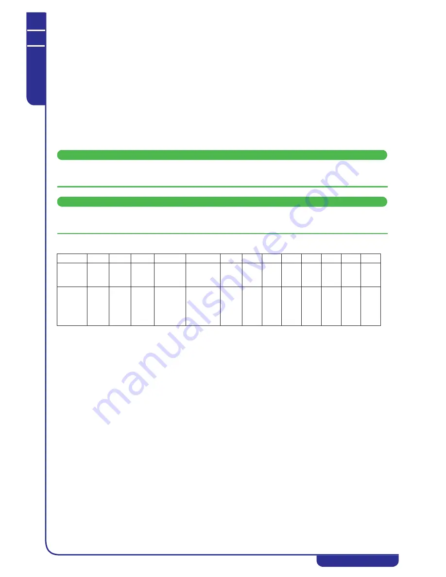
The following table shows the type of oil and the quantity in the compressors of the various different models.
5.8.2
Controlling the condensing unit from a digital input (Factory settings)
Model MCCY condensing units leave the factory with parameters set for control of the unit on a digital input in response to a
customer signal. Specifically, the following contacts are provided on the terminal board (see wiring diagram):
1. Terminal board contact for remote ON/OFF digital input (MCCY 013-301);
2. Terminal board contact for compressor request digital input (MCCY 013-301);
3. Terminal board contact for second compressor request digital input (MCCY 211-301);
4. Terminal board contact for general alarm output (MCCY 013-301);
5.8.3
Controlling the condensing unit from BEWOT and BEWIT temperature
probes
If the customer wishes to use evaporator inlet (BEWIT) and outlet (BEWOT) water temperature probes the operations
described below must be carried out:
1. Disconnect the relays utilised for control of the compressor/s (see wiring diagram)
2. Install the BEWIT evaporator water inlet temperature probe (supplied with the unit) by connecting it to the
dedicated terminal (see wiring diagram). The probe is utilised for temperature control functions.
3. Install the BEWOT evaporator water outlet temperature probe (supplied with the unit) by connecting it to the
dedicated terminal (see wiring diagram). The probe is utilised for antifreeze functions.
4. Edit the following parameters of the electronic controller in order to enable the probes:
•
CF02 = 0;
•
CF04 = 1;
•
CF05 = 1;
•
CF12 = 0 (visible only on MCCY 211-301 units);
•
CF036 = 0;
•
CF042 = 4;
•
CF043 = 0;
Models
013
015
020
031
051
071
081
101
131
171
211
251
301
Oil
charge
(litres)
0,44
0,50
1,13
1,33
1,57
1,57
3,0
3,3
3,3
6,7
6,3
6,6
6,6
Oil type
LG
FVC6
8D
LG
FVC68
D
LG
FVC68
D
Hatco
FRL 32ST
ISO
viscosity
grade 32
Hatco FRL
32ST
ISO
viscosity
grade 32
Daphe
ne
FVC3
2D
Danfo
ss
POE
SZ
160
Danfo
ss
POE
SZ
160
Danfo
ss
POE
SZ
160
Danfo
ss
POE
SZ
160
Danfo
ss
POE
SZ
160
Danfo
ss
POE
SZ
160
Danfo
ss
POE
SZ
160
Summary of Contents for MCCY-CY013 301
Page 68: ......


