26
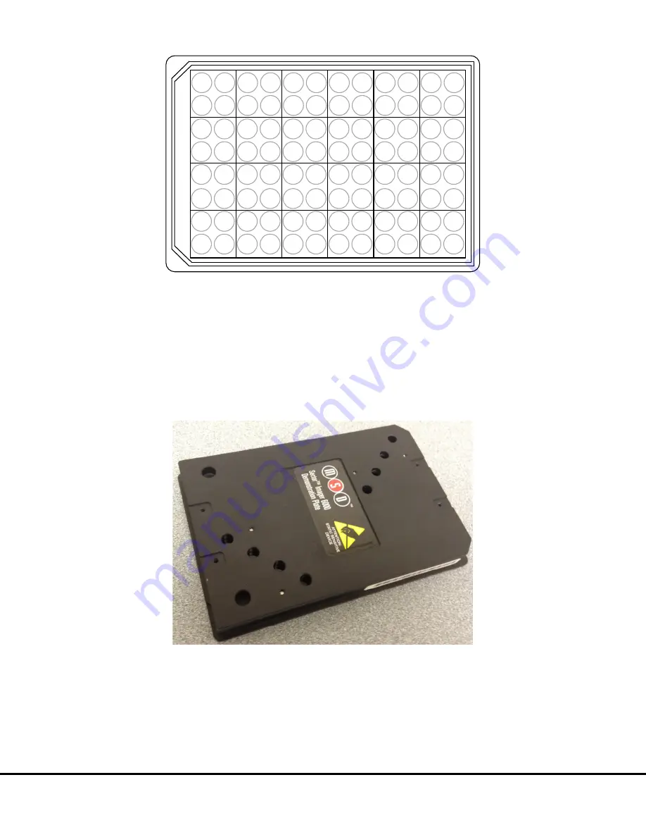
Figure 3:11 The SECTOR 2400/2400A reads 96-well plates in 24 sectors
1 2 3 4 5 6
7 8 9 10 11 12
13 14 15 16 17 18
19 20 21 22 23 24
3.10
SECTOR Imager Demonstration Test Plate
Each SECTOR Imager is shipped with one demonstration plate. This demonstration plate verifies operation of the system and can be
used for operational qualification (OQ). It does not verify performance qualification (PQ) and is not to be used for calibration purposes.
It should be used to verify the function of the SECTOR Imager. The demonstration plate consists of an electronic circuit board housed
in a plastic carrier in the shape of a standard plate. The circuit board for the SECTOR Imager 6000 has six separate sectors, simulating
the structure of MSD MULTI-ARRAY plates (
) as read by the SECTOR Imager 6000. The demonstration plate for the
SECTOR Imager 2400/2400A (not shown) uses a different electrode configuration designed to match the SECTOR Imager 2400/2400A.
Figure 3:12 SECTOR Imager 6000 Demonstration Test Plate
For the SECTOR Imager 6000, sectors 3 and 4 of the demonstration plate have LEDs that test the CCD camera in the SECTOR Imager.
The remaining four sectors of the plate contain known electronic components for testing the electrical functioning of the instrument
across its range of operation. The demonstration plate can be used without any chemical reagents, either to check instrument function
at the start of each day or as a tool for demonstrating the instrument and software to new users. The LEDs for the SECTOR Imager
2400/2400A demonstration plate are in sectors 5, 12, 14, and 19.
Store the demonstration plate in its custom case when not in use, and keep the demonstration plate clean and free of dust and debris.
Summary of Contents for SECTOR Image 2400
Page 1: ...SECTOR Imager Models2400 6000 INSTRUMENT MANUAL www mesoscale com ...
Page 6: ...6 1 Introduction ...
Page 9: ...9 2 ImportantInformation ...
Page 15: ...15 3 SystemDescription ...
Page 28: ...28 4 Installation ...
Page 30: ...30 5 QuickStart ...
Page 36: ...Quick Start 36 Figure 5 8 SECTOR Imager window Run Options dialog box ...
Page 38: ...38 6 UsingtheSECTORImager ...
Page 42: ...42 7 Maintenance ...
Page 45: ...45 8 Appendix ...
Page 54: ...54 9 TechnicalSupport ...
Page 56: ...Technical Support 9 2 ...


