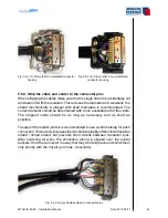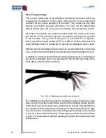
MTUX/IA-63-00 – Installation Manual
45
Date: 2017/02/17
00
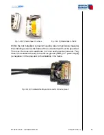
Fig. 5.6.4 (2) Kapton tape in the base
Fig. 5.6.4 (3) Kapton tape in the lid
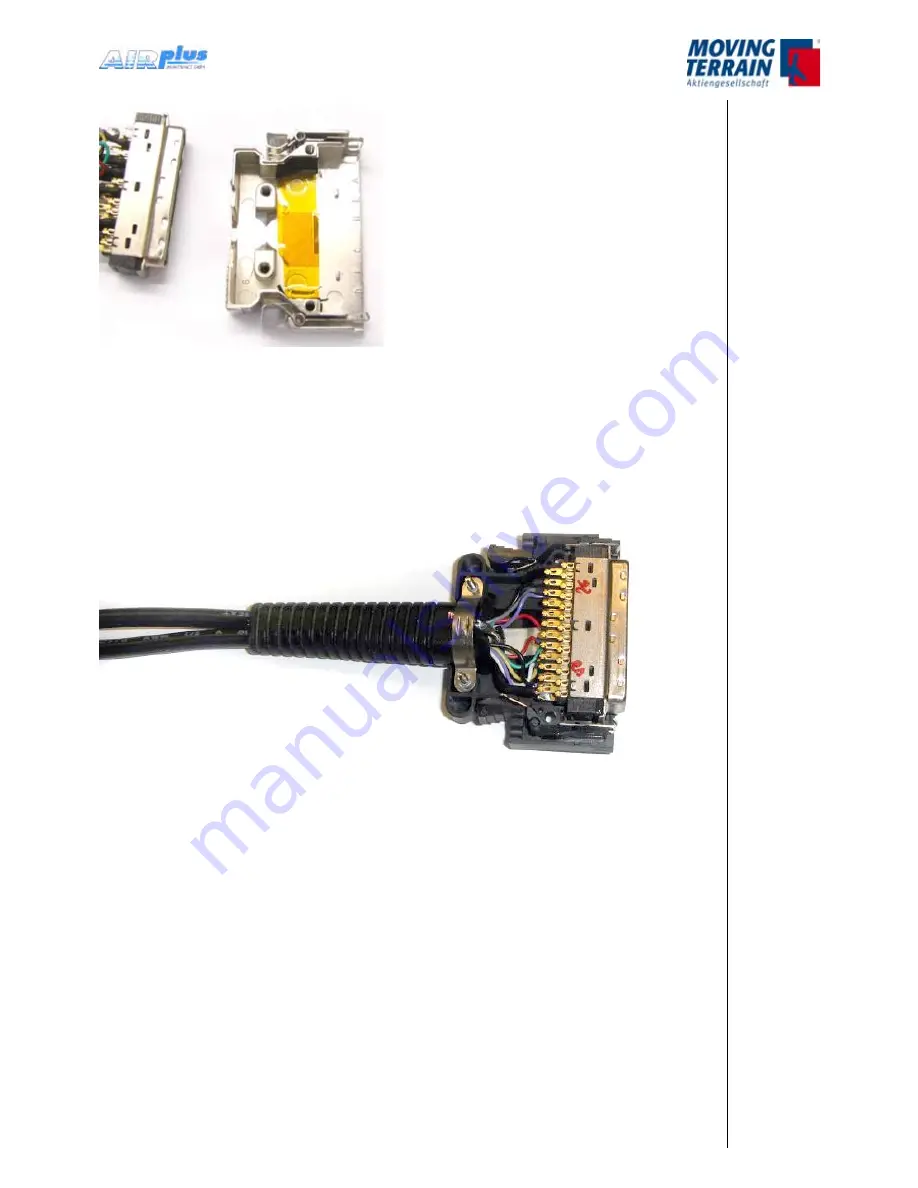
Within the not metallized connector housing (due to mechanical reasons)
the shielding as well as the frame of the connector itself must be grounded.
This must be done with additional (in cross section wider) strands. They
have to be soldered directly to the device ground (GND pin = power supply
(ie negative) in the plug and to the shielding / the frame.
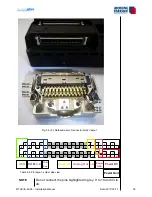
Fig. 5.6.4 (4): Soldered shieldings and connector to device ground
Summary of Contents for MT-VisionAir X ETSO
Page 10: ...MTUX IA 63 00 Installation Manual 10 Date 2017 02 17 INTENTIONALLY LEFT BLANK ...
Page 12: ...MTUX IA 63 00 Installation Manual 12 Date 2017 02 17 INTENTIONALLY LEFT BLANK ...
Page 28: ...MTUX IA 63 00 Installation Manual 28 Date 2017 02 17 INTENTIONALLY LEFT BLANK ...
Page 107: ...MTUX IA 63 00 Installation Manual 107 Date 2017 02 1700 12 4 Dimensions in mm ...
Page 112: ...MTUX IA 63 00 Installation Manual 112 Date 2017 02 17 13 3 Dimensions in mm ...
Page 125: ...MTUX IA 63 00 Installation Manual 125 Date 2017 02 1700 INTENTIONALLY LEFT BLANK ...
Page 137: ...MTUX IA 63 00 Installation Manual 137 Date 2017 02 1700 ...
Page 138: ...MTUX IA 63 00 Installation Manual 138 Date 2017 02 17 ...
Page 139: ...MTUX IA 63 00 Installation Manual 139 Date 2017 02 1700 INTENTIONALLY LEFT BLANK ...
Page 146: ...MTUX IA 63 00 Installation Manual 146 Date 2017 02 17 INTENTIONALLY LEFT BLANK ...

