

MTUX/IA-63-00 – Installation Manual
102
Date: 2017/02/17
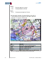
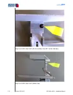
Air traffic within the optical range of the PowerFLARM sensor is displayed on
the chart in relation to the terrain.
If the scale of the chart is too detailed to display all detected aircraft the symbols
are displayed on the rim of the screen in correspondent position.
To see the position of the airtraffic on the chart choose → ZOOM → ZOOM-
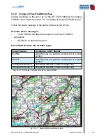
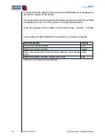
Color coding of traffic deteced by PowerFlarm for all types of signals
Aircraft symbol
Colour
Above the critical cylinder
blue
Below the critical cylinder
brown
Within the height of the critical cylinder, distance out of danger
zone
white
Within the critical cylinder, dangerously close
red
Table 10.2.7 (2): Display of PowerFLARM data
Summary of Contents for MT-VisionAir X ETSO
Page 10: ...MTUX IA 63 00 Installation Manual 10 Date 2017 02 17 INTENTIONALLY LEFT BLANK ...
Page 12: ...MTUX IA 63 00 Installation Manual 12 Date 2017 02 17 INTENTIONALLY LEFT BLANK ...
Page 28: ...MTUX IA 63 00 Installation Manual 28 Date 2017 02 17 INTENTIONALLY LEFT BLANK ...
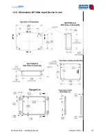
Page 107: ...MTUX IA 63 00 Installation Manual 107 Date 2017 02 1700 12 4 Dimensions in mm ...
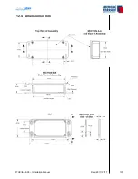
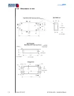
Page 112: ...MTUX IA 63 00 Installation Manual 112 Date 2017 02 17 13 3 Dimensions in mm ...
Page 125: ...MTUX IA 63 00 Installation Manual 125 Date 2017 02 1700 INTENTIONALLY LEFT BLANK ...
Page 137: ...MTUX IA 63 00 Installation Manual 137 Date 2017 02 1700 ...
Page 138: ...MTUX IA 63 00 Installation Manual 138 Date 2017 02 17 ...
Page 139: ...MTUX IA 63 00 Installation Manual 139 Date 2017 02 1700 INTENTIONALLY LEFT BLANK ...
Page 146: ...MTUX IA 63 00 Installation Manual 146 Date 2017 02 17 INTENTIONALLY LEFT BLANK ...