


9 Devices
Rev. 02/2018
83
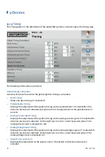
The views are described as follows.
Cyl. / Output column
If cylinder names have been assigned in the configuration of the ignition
controller, they are displayed in the
Cyl.
column. If no cylinder names have
been assigned in the configuration of the ignition controller, the
Output
column with the corresponding ignition output numbers (
A 1
,
A 2
, ...) is
displayed instead.
Firing Angles
The firing angles of the cylinders (
Cyl.
) are displayed in °crankshaft for each output of the
ignition controller.
With the
button you can switch the display of the firing angles:
–
Absolute
: Firing angle in °crankshaft related to the top dead center of the first cylinder in
firing order
–
Relative
: Firing angle in °crankshaft related to its own top dead center
Summary of Contents for PoewerView3
Page 1: ...PowerView3 HMI Module Operating Manual P N 01 10 015 EN Rev 02 2018...
Page 16: ...4 Product Description 16 Rev 02 2018...
Page 17: ...4 Product Description Rev 02 2018 17...
Page 18: ...4 Product Description 18 Rev 02 2018...
Page 19: ...4 Product Description Rev 02 2018 19...
Page 26: ...4 Product Description 26 Rev 02 2018 4 1 8 Overview Drawings Rear View...
Page 27: ...4 Product Description Rev 02 2018 27 Plan View Side View...
Page 137: ...Rev 02 2018 137...
Page 138: ......


