


7 Wiring of the Device
Rev. 02/2018
37
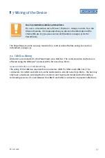
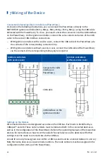
CAN bus wiring
Note the following when connecting the CAN bus:
–
Each bus end must be fitted with a terminating resistor of 120 Ω (see
drawing).
–
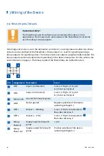
The maximum wire length depends on the bit rate:
Bit rate
Maximum wire
length
Maximum length
of a stub
Maximum length
of all stubs
1 Mbit/s
25 m (82')
1.5 m (5')
7.5 m (25')
800 kbit/s
50 m (164')
2.5 m (8')
12.5 m (41')
500 kbit/s
100 m (328')
5.5 m (18')
27.5 m (90')
250 kbit/s
250 m (820')
11 m (36')
55 m (180')
125 kbit/s
500 m (1,640')
22 m (72')
110 m (360')
50 kbit/s
1,000 m (3,280')
55 m (180')
275 m (902')
–
Only use cables that are specified by the manufacturer for use in the
CAN bus.
The PowerView3 is delivered with a bit rate set to 250 kbit/s.
Summary of Contents for PoewerView3
Page 1: ...PowerView3 HMI Module Operating Manual P N 01 10 015 EN Rev 02 2018...
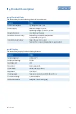
Page 16: ...4 Product Description 16 Rev 02 2018...
Page 17: ...4 Product Description Rev 02 2018 17...
Page 18: ...4 Product Description 18 Rev 02 2018...
Page 19: ...4 Product Description Rev 02 2018 19...
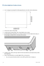
Page 26: ...4 Product Description 26 Rev 02 2018 4 1 8 Overview Drawings Rear View...
Page 27: ...4 Product Description Rev 02 2018 27 Plan View Side View...
Page 137: ...Rev 02 2018 137...
Page 138: ......


