


8 General Operation
48
Rev. 02/2018
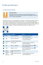
Symbol
Function
This button informs about the status of the access control:
–
Operator
,
Service
,
Master
: The corresponding access level is set.
–
Locked
: The
Read Only
access level is set.
–
Disabled
: The access control is disabled.
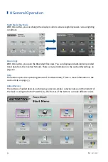
By tapping this button, you can access the
Access Control
view. There is
more information in the section
Access Control
on page 65.
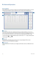
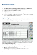
Status information of added devices is shown in the lower field of the
menu bar.
The database symbol provides information on the following states:
Trend data of added devices are recorded on the SD card inserted
in the PowerView3.
An error has occurred while recording the trend data (e. g.
insufficient memory space on SD card, SD card not readable).
The communication status symbol provides information on the following
states:
There is a connection to all added devices.
The connection is not established to all added devices.
No device is connected.
The system time is displayed at the very bottom.
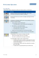
If you tap the button for the connection status, the
Event Log
view opens.
There is more information in the section
Event Log
on page 72.
Summary of Contents for PoewerView3
Page 1: ...PowerView3 HMI Module Operating Manual P N 01 10 015 EN Rev 02 2018...
Page 16: ...4 Product Description 16 Rev 02 2018...
Page 17: ...4 Product Description Rev 02 2018 17...
Page 18: ...4 Product Description 18 Rev 02 2018...
Page 19: ...4 Product Description Rev 02 2018 19...
Page 26: ...4 Product Description 26 Rev 02 2018 4 1 8 Overview Drawings Rear View...
Page 27: ...4 Product Description Rev 02 2018 27 Plan View Side View...
Page 137: ...Rev 02 2018 137...
Page 138: ......


