2-8
Overview
Controls and Indicators
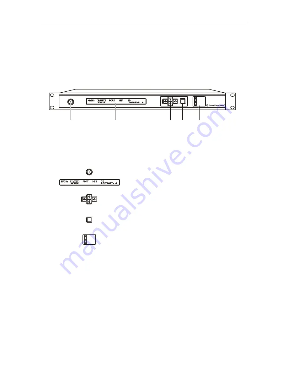
The OM 1000 controls and indicators, as well as the RF monitor jack, are located on the front
panel. Figure 2-6 illustrates the front-panel controls and indicators:
Figure 2-6
OM 1000 front panel
TES T
-2 0dB
PO WER
DATA IN
EX T S YNC
PL L E RROR
RF E RROR
FA ULT SUMM
OM 1000
ENT
A
C
D
E
B
Table 2-3 summarizes the function of the RF monitor jack and each control/indicator:
Table 2-3
OM 1000 front panel RF monitor jack, controls, and indicators
Key Control/Indicator
Description
A
TES T
-20dB
–
20 dB
TEST
RF monitor jack enables convenient monitoring of
the RF output at the front panel. This is an F-type connector.
B
The status display is a two-line, 40-character-per-line,
dot-matrix, high-contrast backlit LCD.
C
The menu select keys are a four-button cluster of up/down and
left/right keys that enable configuration and setup of OM 1000
operating modes. The keys are set flush with the level of the
front panel to minimize the potential for accidental operation.
D
ENT
The
ENT
key enables activation of keypad data. It adds security
by preventing single-button operation from changing the unit
configuration.
E
POWER
DATA IN
EXT SYNC
PLL ERROR
RF E RROR
FAULT SUMM
The LEDs indicate OM 1000 operating status and error
conditions. Refer to Section 5, “Troubleshooting”, for details on
each status LED.
OM 1000 Installation and Operation Manual


