


43
7.6.2 Connection and configuration
The ultrasonic sensors are connected to the MVS system
via the separate control unit MVCU1300-1.
Die MVCU 1300-1 wertet die Signale der Sensoren aus,
die grafischen Overlays und die Einstellung der
Warnbereiche erfolgt über die Bedienoberfläche des MVS-
Systems.
The CAN bus is used to connect the MVCU 1300-1 to the
video control unit MVCD1000-x / MVCD1001-x. The
connection is made via the CAN 2 input.
PLEASE NOTE
When using systems with optional ultrasonic sensors, the
operator control unit must be connected to the video
control unit during the initial start-up via the Y-CAN cable
MK911.
After the initial start-up, the Y-CAN cable can be
removed.
Detailed information on how to install the MVCU 1300-1
can be found in the corresponding installation and
operating instructions.
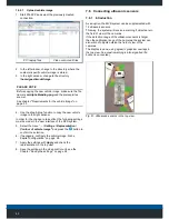
7.6.3 Configuration
In order to display the objects detected by the ultrasonic
sensors in the top view, it is necessary to enter the
horizontal position of each individual sensor into the
system.
Fig. 52: Sensor position coordinate system
S1 Coordinate origin at the left side of the vehicle
S2 Coordinate origin at the front of the vehicle
S3 Coordinate origin at the right side of the vehicle
S4 Coordinate origin at the rear of the vehicle
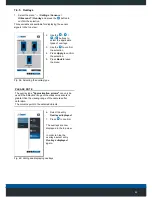
1.
Select the menu “
... / Settings / Sensors /
Ultrasound"
and press the
button to confirm the
selection.
2. Select the entry
New
Sensor
.
3. Press
to confirm.
Fig. 53: Install new sensor
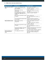
4. Use the
button
to select the sensor
type.
5. Select the
Sensor ID
slider and use the
button to set a
definite sensor ID.
6. Press
Apply
to confirm
the selection.
Fig. 54: Selecting a sensor type