


33
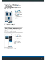
Fig. 34: The manual calibration is completed
10. Press
to confirm.
11. Use
to change to the top view and check the result
of the calibration.
12. If the calibration was successful, use the
button to
return to the user interface and save the calibration by
selecting the menu item "...
/ Settings / Save".
See chapter "Saving the settings" on page 28.
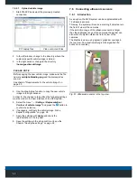
7.3 Control lines
7.3.1 Introduction
The video control unit has four control inputs that can be
configured at random.
A particular display mode can be assigned to each control
input. In addition to the top view, individual cameras can
also be displayed in a split screen view or as a full screen.
For this purpose, the control inputs are connected to the
corresponding signals from the vehicle’s electrical system
(e.g., reverse gear, indicators, etc.).
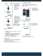
Top view + Rear view
camera
Top view + Camera on
right-hand side
Fig. 35: Split screen view (examples)
If the relevant inputs are subsequently activated by
engaging the reverse gear or turning on the indicator, the
video control unit automatically switches to the
corresponding image.
7.3.2 Requirements
• The control inputs are wired with the vehicle signals
according to the Chapter"Electrical connections" on
page 18.


