background image

46

2

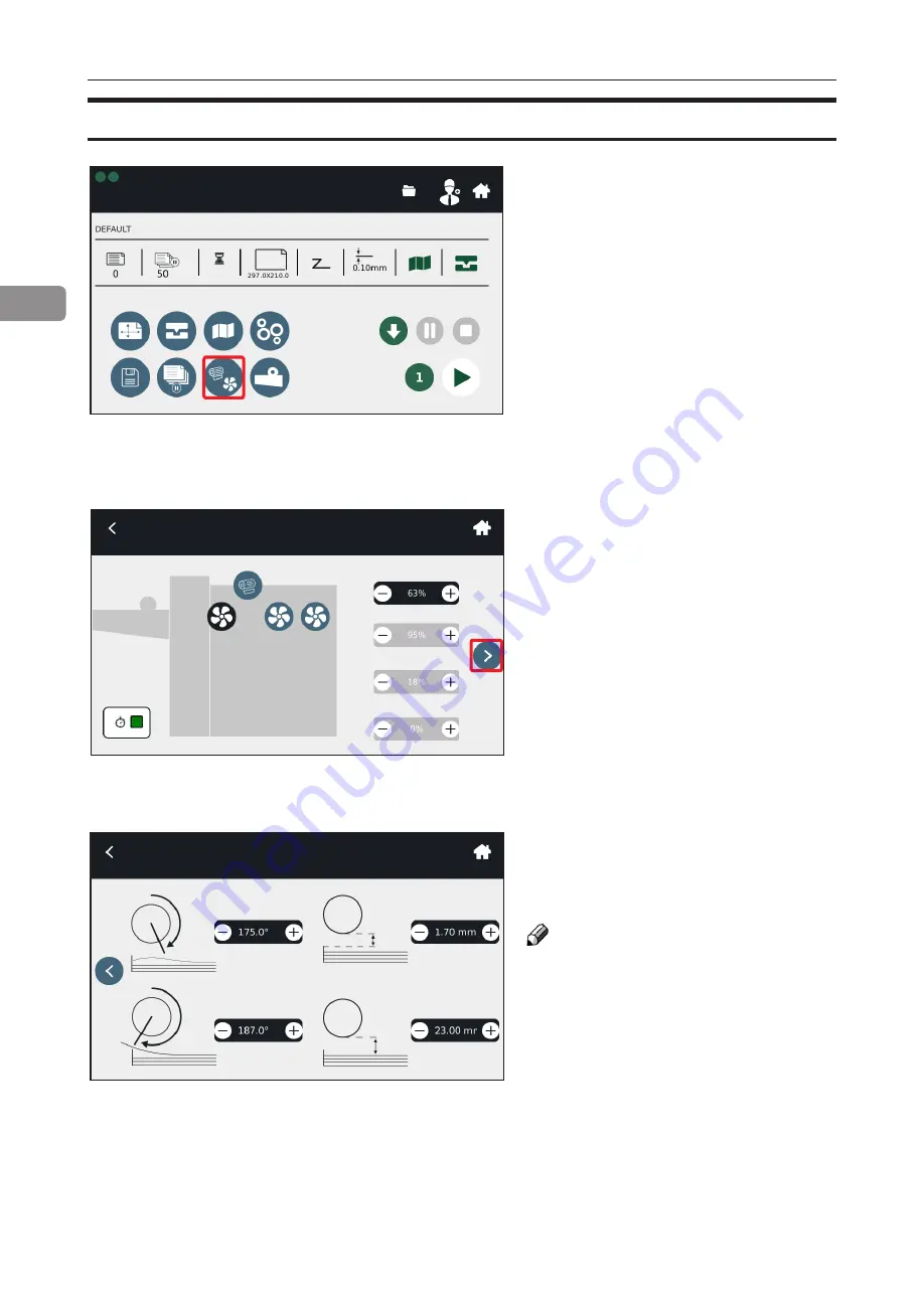
Fans and Choke settings

Fans and Choke settings 

Select the marked button to enter this 

sub-menu.

If automatic settings provide 

unsatisfactory results, fan settings 

may be adjusted manually from 

within this sub-menu. 

Press the marked arrow to get to the 

Choke settings menu.

From this sub-menu the user can 

adjust Choke settings manually. 

NOTE:

See “troubleshooting“ section for 

more information about fan and 

choke adjustment.

MyBinding.com

5500 NE Moore Court 

Hillsboro, OR 97124 

Toll Free: 1-800-944-4573 

Local: 503-640-5920

Summary of Contents for AutoCreaser Pro 385

Page 1: ...Morgana AutoCreaser Pro 385 High Speed Creasing Machine with Deep File Feeder Instruction Manual ...

Page 2: ...ndy for future reference For safety please follow the instructions in this manual Doc no T10202A Date 02 Dec 2016 Operating Instruction Morgana Pro 385 Feeder Creaser Folder MyBinding com 5500 NE Moore Court Hillsboro OR 97124 Toll Free 1 800 944 4573 Local 503 640 5920 ...

Page 3: ...uate measures The product System which is connected to this machine will be class A NOTE The domestic environment is an environment where the use of broadcast radio and television receivers may be expected within a distance of 10m of the apparatus concerned MyBinding com 5500 NE Moore Court Hillsboro OR 97124 Toll Free 1 800 944 4573 Local 503 640 5920 ...

Page 4: ...if instructions are not followed could result in death or serious injury CAUTION Indicates a potentiality hazardous situation which if instructions are not followed may result in minor or moderate injury or damage to machine or property NOTE This sign refers to Remarks for making the operation much easier You get practical hints or knowledge to assist you in the machine operation such as Preparati...

Page 5: ...result in electrical shock Never connect the machine to a power source that lacks a ground connection terminal This machine is destined for specific purpose only Any use going beyond this specific purpose is re garded as beyond the determination The manufacturer will not be liable for damages resulting from any use beyond the determination unallowed operation respectively The user alone bears the ...

Page 6: ...equipment Do not move the machine while the machine is running Do not open covers while the machine is running Do not switch off the power while the machine is running Make sure the machine cycle has ended Lay the power cord in a way that nobody will stumble over it Do not place things on the cord Never attempt any maintenance function that is not specifically described in this documentation Alway...

Page 7: ...Page intentionally blank MyBinding com 5500 NE Moore Court Hillsboro OR 97124 Toll Free 1 800 944 4573 Local 503 640 5920 ...

Page 8: ...lt Knobs 23 Folding 26 About the Fold 26 Deflects 29 About Deflects 29 Perforating 30 Using the perforation 30 Turning On Off the Power 32 Main Power Switch 32 Calibration 33 Sensor Calibration 33 Stop Gate Distance Calibration 33 Folder Bypass Tray Installation 34 2 Setting Up a Job 35 Quick Start 35 The Run Screen 37 Modifying Settings 38 Paper Size and Thickness 38 Crease Settings 39 Pro 385 Qu...

Page 9: ...ed Jam in Feeder Area 59 Jam between Units or Jam in Creaser Folder 60 Recommended Settings Adjustments 61 5 Troubleshooting Fault Codes 63 Pro 385 Fault codes 63 General 63 Pro 385 Jam Codes 64 Pro 385 Error Codes 69 6 Remarks 73 Do s And Don ts 73 Where to Put Your Machine 74 Machine Environment 74 Power Connection 74 Access to Machine 75 Maintaining Your Machines 76 Pro 385 Maintenance 76 Limit...

Page 10: ...4 sheets per hour The Feeder Creaser configuration allows for automatic sheet feeding and single or dual static creasing accurate to within 0 1 mm This configuration can crease and or perforate sheets accurately at a rate of 8 500 A4 sheets per hour After creasing the finished products are collected neatly on a stacking tray The Feeder Folder configuration allows for automatic sheet feeding dynami...

Page 11: ... Vacuum Fan Assy 8 Paper Guides 9 Vacuum Drum Drum Guard 10 Ultrasonic Double Sheet Detection USDSD Sensor Q10 1 2 3 4 5 6 8 17 16 15 14 13 12 7 9 10 11 11 Exit Feed Sensor Q7 12 Paper Stop Gate 13 SP Sensor 14 Side Lay w Separation Fans 15 Latching handles 16 Paper Backstop 17 Paper Weight MyBinding com 5500 NE Moore Court Hillsboro OR 97124 Toll Free 1 800 944 4573 Local 503 640 5920 ...

Page 12: ...3 Articulating Rigid Foot 4 Caster 5 Indexing Lever 6 Stacker Tray 7 Stacker Guides 8 Creaser Assembly Exit 9 Antistatic Kit optional 10 Static Creaser Assembly 2 11 Static Creaser Assembly 1 12 Entry Sensor Q20 13 Exit Sensor Q25 4x 4x MyBinding com 5500 NE Moore Court Hillsboro OR 97124 Toll Free 1 800 944 4573 Local 503 640 5920 ...

Page 13: ...Delivery Module Handle 6 Delivery Module 7 Stacker Guides 8 Folding Roller Assembly 9 Fold Knife K1 Sensor Q45 10 Exit Sensor Q52 2 4x 4x 11 Power Signal Connector 12 Interlock 13 Antistatic Kit optional 14 Dynamic Creaser Assembly 15 Static Creaser Assembly 16 Entry Sensor Q40 MyBinding com 5500 NE Moore Court Hillsboro OR 97124 Toll Free 1 800 944 4573 Local 503 640 5920 ...

Page 14: ...nguages Detailed descriptions of each menu and sub menu are found in this Operator Manual NOTE Depending on modules and features installed the screen may look different from what you see here Some functions are greyed out or not visible at all and remaining buttons may stretch to fit the screen This manual will most often show a fully configured system Control Panel Intro Page Turning on the Morga...

Page 15: ...lecting the play button on the Home Screen This screen displays paper parameters job status and system status The operator can start edit pause or abort the job from this screen MyBinding com 5500 NE Moore Court Hillsboro OR 97124 Toll Free 1 800 944 4573 Local 503 640 5920 ...

Page 16: ... Description 1 99 35 1 Anvil Set 1 99 12 1 28T Slitter Perforator blade 601 185 1 Sensor Cleaning Brush 601 118 1 Wooden Handled Brush 601 119 2 Disposable Latex Glove Size XL 90 031 1 Instruction Sht Roller C T 302A 2 Blade Removal Tools 170 101 02 1 Installation Setup DigiFold Tools and Accessories Below are the lists of the tools and accessories included in the despatch kits both for the AutoCr...

Page 17: ... 99 10 20T Slitter Perf Set 1 99 13 Slitting Blade Set 1 99 41 56T Slitter Perf Set 1 99 42 96T Slitter Perf Set 336 03 02 Blade Set Narrow for Static Creaser 336 30 01 Cross Perf Blade Set up to 150mm for Static Creaser 176 213 01 Blade Set Narrow for DynaCrease 176 213 03 Blade Set Ultra Narrow for DynaCrease Below are the lists of the optional parts that can be ordered by the user both for the ...

Page 18: ...o stop any problems that they might cause Guidelines Always make sure that the sheets of paper you use are cut square This machine is designed to fold the paper at right angles It cannot do this if the paper edges are not cut at 90 angles to each other Always make sure that all of the paper for a job is cut the same This machine uses the sheet length that you set to automatically set the crease an...

Page 19: ...pressure on the paper This pressure compresses the substrate and printed image which makes the paper thin and weak along the edges of the crease This allows the paper to fold accurately along the crease NOTE When you crease and fold the crease is the most important process The paper will not fold accurately if the crease is not made correctly or if it is not made in the correct position Creasing A...

Page 20: ... also available for purchase The Ultra Narrow blade set is designed to make a very narrow crease One should use an ultra narrow blade set if folding very thin paper paper thickness close to the minimum specification for this machine Always make sure you have the correct blade set installed before starting a job When running into creasing or folding problems try a different blade set This can help ...

Page 21: ...Switch the machine off 3 Lift the top cover 4 Using a 5mm allen key remove the two socket head screws one at each end of the Blade Set A Replacing Blade Sets A B 6 The Blade Set can now be removed from the machine using the Blade Extractor Tools C 5 Remove the Sheet Guide Assembly by pulling upwards on the two flanges one at each end as shown B C ...

Page 22: ...The Lip of The Blade Adjuster Assembly 9 Slide the blade assembly out of the creasing unit and lay it on a flat surface 10 Slide the blade adjustment cams and the blade adjustment assemblies away from the dowels located in the ends of the blades anvils as shown in the figure below 8 Pull the Blade Assembly in the direction shown to unclip and release the Blade Set ...

Page 23: ...e can be changed to have the ANVIL at the top which may improve the repeatability of the fold relative to the crease for certain fold types or when using lighter stocks NOTE For optional blade sets see Optional Parts in this section 13 Rotate the blade adjustment cams until they are just tight and then back off slightly Switche the machine on reset blade to Top Dead Centre and make final adjustmen...

Page 24: ...es are not in the correct position see figure 1 adjustment is needed AutoCreaser Pro 385 Knob Adjustment Procedure Blades 1 and 2 Feed direction Blade 1 Blade 2 figure 1 NOTE Wrong crease positions are marked in red correct crease positions are marked in green Blade 1 knob Blade 2 knob 4 Rotate the knobs counterclockwise to loosen them 5 Move the knob s slightly either to the left or to the right ...

Page 25: ... marked in red correct crease position is marked in green Blade 2 knob 4 If the crease is not in the correct position see figure 2 adjustment is needed If the crease is in the correct position skip steps from 5 to 9 5 Rotate the left knob counterclockwise to loosen it 6 Move the knob slightly either to the left or to the right depending on whether the crease is tilted either to the right or to the...

Page 26: ...o the right depending on whether the crease is tilted either to the right or to the left 16 Rotate the knob clockwise to secure it 17 Run a test sheet to check if the creases is now perpendicular 18 Repeat steps 14 to 17 if necessary 10 From the GUI select a one crease custom fold see section 2 and load paper 11 Turn the folding option off see section 2 12 Run a test sheet see section 2 13 If the ...

Page 27: ...el folds on each sheet A cross sectional view of the fold mechanism is shown below This machine has many different fold configurations available The fold configurations are shown in detail on your Quick Reference Sheet and in Section 2 of this manual Folding About the Fold Fixed Roller Roller Gap 1 Roller Gap 2 2nd Fold Knife K2 1st Fold Knife K1 Roller Gap 3 MyBinding com 5500 NE Moore Court Hill...

Page 28: ...X X X Concertina 3X X X While setting up a job the roller gaps are set to specified distances automatically If results are unsatisfactory i e cracking of the print is noticeable these gaps may need to be adjusted manually to improve results The table below details the default values for the roller gaps per fold setting MyBinding com 5500 NE Moore Court Hillsboro OR 97124 Toll Free 1 800 944 4573 L...

Page 29: ...ck sheet of A4 paper X is equal to 0 10 mm and the Roller Gaps are automatically set to the following values Gap 1 X 0 10 mm Gap 2 2X 0 20 mm Gap 3 2X 0 20 mm If cracking of the print is noticeable or if jams are frequently occuring these gaps may be manually adjusted see roller adjustment section 2 MyBinding com 5500 NE Moore Court Hillsboro OR 97124 Toll Free 1 800 944 4573 Local 503 640 5920 ...

Page 30: ...ith the lead edge or spine of the document to guide it through the machine A Half Fold K1 cycle means K1 folds the paper and K2 deflects the paper This leads to a round spine finish This cycle is shown below A Half Fold K2 cycle means K1 deflects the paper and K2 folds the paper This leads to a square spine finish This cycle is shown below Deflects About Deflects 1 K2 Deflect K1 Fold 1 2 K2 Deflec...

Page 31: ...away from any obstructing drive wheels or hubs in order to mount the blades The perforator blades are split into two matching halves and are fitted to the drive wheels as shown in the photograph using the four screws supplied A hardened anvil is fitted to the drive hub as shown in the photograph also using the four screws supplied Again the anvils are made from matching halves CAUTION The perforat...

Page 32: ...l against the hub 13Fix the perforator stripper adjacent to the drive wheel and blade as shown 14Operate the machine and test the perforations for form For multiple perforations repeat the above procedure it is reccomended to use a separate perforator for every perforating blade set fitted in the creasing unit A Perforating drive wheel with mounted blades B Drive hub with mounted anvils C Standard...

Page 33: ...r Main Power Switch 1 Ensure that the main power cord is plugged into the wall and to the power socket A of the Pro 385 2 Check that terminator plug B is plugged in the Creaser Folder 3 Toggle on off the Main Power Switch C A C B ...

Page 34: ...to be calibrated Please contact a certified service technician if calibration is required A The position of the stop gate A may need to be calibrated if feed errors begin occuring more frequently Please contact a certified service technician if calibration is required If Stop Gate position needs to be changed see troubleshooting section Stop Gate Distance Calibration A ...

Page 35: ...ove the delivery roller on top of the delivery extension 3 Hold the handle and push it to move the delivery module down 4 Put the Bypass Tray in place and pull the plungers B 5 Release the plungers A B MyBinding com 5500 NE Moore Court Hillsboro OR 97124 Toll Free 1 800 944 4573 Local 503 640 5920 ...

Page 36: ... for operator safety The Main Menu will not come up unless the operator acknowledges he or she is trained to operate the machine Quick Start Screen 1 Paper Format Orientation The Paper Format sub menu allows for selection of standard formats Toggle between portrait and landscape by pushing the marked button NOTE Due to physical constraints only A4 sheets may be rotated in this machine Quick Start ...

Page 37: ... near the machine for operator reference A Letter Fold B Concertina Fold C Half Fold Knife 2 D Half Fold Knife 1 E Engineering Fold F Gate Fold G Closed Gate Fold H Hinge Fold I Double Parallel Fold A D G B E H C F I Wait Screen After selecting the fold configuration the Pro385 will perform initialisation The wait screen will appear for a few seconds until initialisation is complete MyBinding com ...

Page 38: ...tal number of sheets processed B Batch Setting Current batch setting e g 50 sheets 100 sheets etc C Batch Pause Setting Shows a flag for automatic off manual start mode and a timer for 3 second pause mode D Paper Size Job paper size E Fold Setting Job fold setting F Paper Thickness Job paper thickness G Fold Knives On Off Toggles the fold knives on and off H Crease Blades On Off Toggles the crease...

Page 39: ...er size by adjusting the values at the bottom of the screen Paper Orientation Toggle between portrait and landscape by pushing the marked button NOTE Due to physical constraints only A4 sheets may be rotated in this machine Paper Size and Thickness Modifying Settings Paper Thickness The proper paper thickness must be selected so that machine parameters are set correctly for optimal performance It ...

Page 40: ... folding options are described below A D G B E H C F I J A Letter Fold B Concertina Fold C Half Fold Knife 2 D Half Fold Knife 1 E Engineering Fold F Gate Fold G Closed Gate Fold H Hinge Fold I Double Parallel Fold J Custom Crease NOTE Some options might be greyed out depending on modules and features installed Crease Settings ...

Page 41: ... are the default crease positions NOTE Tapping on a value opens a type box Switching the crease on off Press the marked button to switch the crease on off The standard creasing and folding process for each folding option is detailed in the next page in the Pro 385 Quick Reference Sheet This sheet comes with your machine and should be kept available near the machine for operator reference MyBinding...

Page 42: ...1 2 3 Fold 2 Fold 1 Engineering Fold 1 2 3 Fold 2 Fold 1 Gate Fold 1 2 3 Fold 2 Fold 1 Closed Gate Fold Crease 2 FRONT FRONT Fold 1 Crease 3 Fold 2 Crease 1 1 2 3 Fold 2 Fold 1 Letter Fold 1 2 3 Fold 2 Fold 1 Concertina Fold 1 2 3 Fold 2 Fold 1 MyBinding com 5500 NE Moore Court Hillsboro OR 97124 Toll Free 1 800 944 4573 Local 503 640 5920 ...

Page 43: ...ases per job Adjusting the crease position The operator can adjust the position of the creases on the paper by increasing decreasing the values NOTE Tapping on a value opens a type box Custom Crease Custom crease Press the marked button to enter this sub menu This page allows the user to customize the number and the position of the creases on the sheets When opened this menu will list the creases ...

Page 44: ... a value opens a type box Switching the fold on off Press the marked button to switch the fold on off Install Bypass Tray If the folding option is not in use the Bypass Tray needs to be installed on the machine while the Delivery Module needs to be lowered When switching the fold off this screen will remind the user to install the Bypass Tray and lower the Delivery Module see section 1 for how to ...

Page 45: ...ttings are not working properly See folding section in this manual for more information on roller gaps Roller Gap Adjustment Raise the Delivery Module When switching the fold on this screen will remind the user to take the Bypass Tray off and raise the Delivery Module Press the green checkmark button after having completed the operation MyBinding com 5500 NE Moore Court Hillsboro OR 97124 Toll Fre...

Page 46: ...hin this sub menu Batch Jobs Select batches of 50 100 150 sheets The operator can also enter a custom number of sheets by pressing the calculator button Select the hourglass button for the 3 second pause mode between the batches select the flag for the manual start mode between the batches Save a Job MyBinding com 5500 NE Moore Court Hillsboro OR 97124 Toll Free 1 800 944 4573 Local 503 640 5920 ...

Page 47: ...ettings may be adjusted manually from within this sub menu Press the marked arrow to get to the Choke settings menu From this sub menu the user can adjust Choke settings manually NOTE See troubleshooting section for more information about fan and choke adjustment MyBinding com 5500 NE Moore Court Hillsboro OR 97124 Toll Free 1 800 944 4573 Local 503 640 5920 ...

Page 48: ...lly by the user with custom settings Increase decrease value A to change distrance between the sheets delivered Increase decrease value B to change the delivery roller positon NOTE Tapping on a value opens a type box A B Lower Paper Tray Pressing this button moves the paper tray down to allow for loading more paper Lower Paper Tray MyBinding com 5500 NE Moore Court Hillsboro OR 97124 Toll Free 1 8...

Page 49: ...o hold the job Press the stop button to abort the job Running Test Sheets Action Buttons Creating and Saving Jobs Select the marked button to access all saved jobs The user can create new jobs edit delete open and save jobs from within this menu Creating and Saving Jobs MyBinding com 5500 NE Moore Court Hillsboro OR 97124 Toll Free 1 800 944 4573 Local 503 640 5920 ...

Page 50: ...e them by pressing the save changes button The create new job button is used to create a new job from blank Home Select this button to get back to the quick start screen Expert User Options Press the marked button to access expert user options See section 3 expert user options for more details on this submenu Home Expert User Options MyBinding com 5500 NE Moore Court Hillsboro OR 97124 Toll Free 1...

Page 51: ... paper size is that of the last job used If the paper size is correct press the green checkmark button the Pro 385 will start the initialisation Job completed Check Paper Size If the paper size is not correct select the x button and remove the paper from the stack support Press the green checkmark button to allow the Pro 385 for initialisation once the paper has been removed MyBinding com 5500 NE ...

Page 52: ...fans choke and delivery module according to the numbering of the picture above If you do not follow this order some of the changes might be discarded For example adjusting the paper thickness value after having modified the fan settings will automatically reset the fan values to default 1 4 6 2 3 5 MyBinding com 5500 NE Moore Court Hillsboro OR 97124 Toll Free 1 800 944 4573 Local 503 640 5920 ...

Page 53: ...cut the paper Always make sure that the crease pressure is set correctly Set the crease pressure prior to running the machine when creases are not as desired and when replacing crease blade sets Loading Paper Crease Pressure Job Preparation 1 Choose paper size in Graphical User Interface Quick Start or Manual selection 2 Open Feeder Top Cover 3 Load Paper NOTE Paper Size parameters must be chosen ...

Page 54: ... are just tight and then back off slightly before tightening the socket head screws 6 The diagram below demonstrates the adjustment of the blade pressure NOTE If the crease damages or cuts through the paper decrease the crease pressure by rotating the adjustment cams a small distance towards the infeed side of the machine If the paper cracks along the spine when it is folded increase the crease pr...

Page 55: ...54 2 Page intentionally blank MyBinding com 5500 NE Moore Court Hillsboro OR 97124 Toll Free 1 800 944 4573 Local 503 640 5920 ...

Page 56: ...ed button to switch on off the DSD sensor NOTE The DSD sensor should be turned off only when feeding laminated paper DSD switch button Expert User Menu From within this sub menu the operator can choose between DSD switch button Conversion button Service Settings in production Tools Plint MyBinding com 5500 NE Moore Court Hillsboro OR 97124 Toll Free 1 800 944 4573 Local 503 640 5920 ...

Page 57: ...rvice Menu This is only for certified service technicians Please contact a certified service technician if service is required Service menu Conversion button Press the marked button to toggle between inches and millimiters Conversion button MyBinding com 5500 NE Moore Court Hillsboro OR 97124 Toll Free 1 800 944 4573 Local 503 640 5920 ...

Page 58: ... the desired direction Press the play button to move the knives back and forth Press the stop button to stop the knives Tools menu Press the left and right circular arrows in the bottom left corner to move the knives manually either to the left or to the right The user can also use this sub menu to set blades to Top Dead Centre position by pressing the up arrows on the bottom of the screen See the...

Page 59: ...58 3 Page intentionally blank MyBinding com 5500 NE Moore Court Hillsboro OR 97124 Toll Free 1 800 944 4573 Local 503 640 5920 ...

Page 60: ...t has been misfed and is not damaged reposition and restart 4 If sheet is damaged replace it 5 Once the area has been cleared press the green checkmark button on the screen A Misfeed Jam in Feeder Area Misfeeds Jams MyBinding com 5500 NE Moore Court Hillsboro OR 97124 Toll Free 1 800 944 4573 Local 503 640 5920 ...

Page 61: ...t damaged reposition and restart 3 If the sheet has entered the rollers use the GUI press home then expert then tools and use the arrows to move the rollers 4 Once the area has been cleared press green checkmark button on the screen MyBinding com 5500 NE Moore Court Hillsboro OR 97124 Toll Free 1 800 944 4573 Local 503 640 5920 ...

Page 62: ... Doing so will cause a malfunction FAN3 Power Front and Rear Lead Edge Separation Fans may need to be adjusted to create proper separation within the lead edge of the paper stack FAN4 Power Front and Rear Trail Edge Separation Fans may need to be adjusted to create proper separation within the trail edge of the paper stack Time push the Time button to the increase the vacuum pump activation time T...

Page 63: ...e between the vacuum drum and unseparated paper stack Generally speaking a larger Hsys distance will require higher fan power to achieve desired separation Choke Pick Up and Choke Feed Angle Adjust these parameters to achieve optimal paper pick up and feed locations It is desirable to have the papers fed out tangentially between the stop gate and drum Recommended Settings Adjustments continued Cho...

Page 64: ...r JAM 107 Feeder Exit sensor not activated JAM 201 AutoCreaser Late to Q20 from Q7 JAM 202 AutoCreaser Q20 covered too long JAM 205 AutoCreaser Q21 Blade 1 home sensor not actuated in time during run JAM 206 AutoCreaser Q22 Blade 2 home sensor not actuated in time during run JAM 207 AutoCreaser Late to Q25 from Q20 JAM 208 AutoCreaser Q25 covered too long JAM 301 DigiFold Jam between units B JAM 3...

Page 65: ...Section 4 Misfeed Jam in Feeder Area Lower stop gate Adjust choke feed angle Change choke pick up angle Check if the paper format is the correct one Check paper Backstop Ensure that there are no obstructions in the paper path JAM 103 Feeder Exit Jam A This code is displayed if the DSD Sensor Q10 was activated for too long this means that there is a paper jam between the rollers Actions Shake paper...

Page 66: ... the exit sensor Q7 is not activated during the run This means that the paper got stuck in the feeder Actions See Section 4 Misfeed Jam in Feeder Area Ensure that there are no obstructions in the paper path JAM 106 No Paper No paper checks if sheets are present in the feeder during the feed process A no paper condition is generated if sensor Q11 cannot detect any paper Actions Add paper and remove...

Page 67: ...urs when it takes too long for a paper to cover the distance between sensor Q7 and sensor Q40 This means that the paper got stuck between the rollers Actions See Section 4 Jam in the Folder Check for misfeed sheets debris under the sensor box where Q7 is located Lower FAN1 power Ensure that there are no obstructions in the paper path JAM 206 Q22 Blade 2 home sensor not actuated in time during run ...

Page 68: ...rease pressure Ensure that there are no obstructions in the paper path JAM 306 Fold 1 Sensor not uncovered in time This error occurs when the Q45 sensor is not uncovered in time Actions See Section 4 Jam in the Folder Check paper path in delivery module Ensure that there are no obstructions in the paper path JAM 309 Folder 1 position error This error occurs when the Q41 Blade drive 1 home sensor i...

Page 69: ...ring run Actions Remove any misfed sheet s Check that creaser tools are in open position see setting crease pressure Ensure that there are no obstructions in paper path JAM 315 Edge Sensor not uncovered in time This error occurs when the Q45 sensor is not uncovered in time during run Actions Remove any misfed sheet s Check that papers in stacker do not block exiting papers Ensure that there are no...

Page 70: ... cover the distance between two sensors The line indicates in which module the error has occurred Remove the sheet and press the checkmark button to clear this error Press the arrow button to move the stack support down General Error Code description misfeed This error appears when a sheet has been misfed The line indicates in which module the misfeed has occurred Remove the misfed sheet s and pre...

Page 71: ...pport down Close top cover Close the feeder s top cover to clear this error Press the arrow button to move the stack support down Close feeder s top cover raise the delivery module Close the folder s top cover raise the delivery module to the correct position to clear this error Press the arrow button to move the stack support down MyBinding com 5500 NE Moore Court Hillsboro OR 97124 Toll Free 1 8...

Page 72: ...mark button to clear this error and continue the initialisation DSD error This error message appears if a double sheet feed is detected Remove the misfed sheets and press the checkmark button to clear this error Press the arrow button to move the stack support down NOTE When feeding laminated paper the DSD sensor should be turned off to avoid getting this error See the Expert user options section ...

Page 73: ...72 5 Page intentionally blank MyBinding com 5500 NE Moore Court Hillsboro OR 97124 Toll Free 1 800 944 4573 Local 503 640 5920 ...

Page 74: ...rtified service technician to correct the problem Warning This is a Class A product In a domestic environment this product may cause radio interference in which case the user may be required to take adequate measures NOTE The domestic environment is an environment where the use of broadcast radio and television receivers may be expected within a distance of 10 m of the apparatus concerned Do not s...

Page 75: ...l cause damage to electronics and cause machine malfunctions Always locate the equipment on a solid support surface with adequate strength for the weight of the machine Always keep magnets and all devices with strong magnetic fields away from the machine If the place of installation is air conditioned or heated do not place the machine where it will be Directly exposed to cool air from an air cond...

Page 76: ...igiFold Pro 385 AutoCreaser Pro 385 1500 mm 59 1000 mm 39 4 700 mm 27 6 1000 mm 39 4 Service Access Operator Access 1400 mm 55 1 1000 mm 39 4 700 mm 27 6 Service Access 1000 mm 39 4 Operator Access MyBinding com 5500 NE Moore Court Hillsboro OR 97124 Toll Free 1 800 944 4573 Local 503 640 5920 ...

Page 77: ...e infeed rollers Alternatively it can be blown with compressed air Clip 1 sensor is situated on the lower guides beneath the delivery conveyor and can be cleaned when required using a slim brush Clip 2 sensor is situated on the upper guides inside the top cover and can be cleaned when required using a slim brush Q20 sensor on the Creaser Q40 sensor on the Folder is situated beneath the input rolle...

Page 78: ...0gsm 0 20 x 160gsm 0 25 x 250gsm 0 40 x 350gsm 140 x 210 Min 5000sht 500mm 3250 500 2500 500 2000 500 1250 500 148 x 210 A5 5000 500 3250 500 2500 500 2000 500 1250 500 148 x 315 5000 500 3250 500 2500 500 2000 500 1250 500 210 x 297 A4 5000 500 3250 500 2500 500 2000 500 1250 500 148 x 630 5000 500 3250 500 2500 500 2000 500 1250 500 210 x 445 5000 500 3250 500 2500 500 2000 500 1250 500 297 x 42...

Page 79: ...78 6 Page intentionally blank MyBinding com 5500 NE Moore Court Hillsboro OR 97124 Toll Free 1 800 944 4573 Local 503 640 5920 ...

Page 80: ...er and Creaser Plug in 0 W Sleep Mode 55W Standby lid open 90W Standyby lid closed 180W Power consumption Max 1100W Heat emissions Feeder and Creaser Standby 190 BTU h Max 3800 BTU h Operating temperature 10 30 C Humidity 30 80 RH Sound emissions 80 dB Machine Specifications Folder Pro385 Specifications Remarks Upstream Device Compatibility Feeder Pro385 Power Source 100 240 V 50 60 Hz 6 10 Power ...

Page 81: ... sheets hour Stop Creaser 8500 sheets hour Dynamic Creaser Folder 6000 sheets hour Agency approvals UL EMC Product Length Width Height Weight Feeder Module 1088 mm 42 8 in 693 mm 27 3 in 1073 mm 42 2 in 175 kg 386 lb Creasing Module 328 mm 12 9 in 652 mm 25 7 in 1165 mm 45 9 in 80 kg 176 lb Folder Module 379 mm 14 9 in 652 mm 25 7 in 1265 mm 49 8 in 140 kg 309 lb Stacker Tray Folder 494 mm 19 4 in...

Page 82: ...Sheets are assumed to be perfectly 90 Tolerances are referring to deviations within one job Fold position variation Measurement L1 L2 2 from Sheet to Sheet Crease skew Measurement L1 L2 Fold position Fold position relative to the Crease Position Fold skew Measurement L1 L2 Side registration Offset between one sheet the next perpendicular to the transport direction MyBinding com 5500 NE Moore Court...

Page 83: ...ormáció 13 Aláírva nevében ÍSLENSKA 1 ESB Leyfisyfirlýsing 2 Fjöldi 3 Framleiðandi 4 Þessi samræmisyfirlýsing er sett alfarið á ábyrgð framleiðanda 5 Markmið yfirlýsingarinnar 6 Gerð 7 Tilnefning 8 Lýsing 9 Markmið yfirlýsingarinnar lýst er hér að ofan er í samræmi við viðeigandi Union samhæfingu löggjafar 10 Tilskipun 11 Standard 12 Viðbótarupplýsingar 13 Undirritað fyrir og fyrir hönd ITALIANO 1...

Reviews: