22
7.4 MAX-Alarm
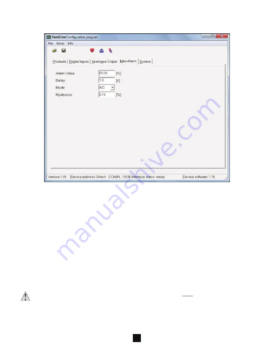
In the first field the ‘alarm value’ is freely definable.
The ‘delay’ describes the desired delay the system needs to complete the switching process. This is in-
tended to avoid changeable “switching” of the switch.
Example:
In Figure 35 the MAX alarm is set to 85% and the alarm delay to 1 second.
If the respective value drops below the alarm value, switching of the alarm does
not take place until after another control value after one second.
In the work ‘mode’ you can set the desired relay contact via the pull-down button. In this case the available
option is either normally opened (NO) or normally closed current (NC).
The alarm ‘hysteresis’ describes the desired delay of the switching process. In this case, however, refer-
ence is made to the desired percentage deviation from the alarm value. It is intended to avoid changeable
“switching” of the switch.
Example:
In Figure 35 the MAX alarm is set to 85% and the alarm hysteresis to 0.1%.
The alarm is thus not triggered until 84,915 or switched off until 85,085.
IMPORTANT: After every setting in the respective screen the data must be transferred to the
Humi
Core
™
Pro
system using the ‘Program parameters’ button! Otherwise there is a risk of losing
the settings (see ‘Program parameters’ in Section 6.3)!
Figure 35


