Mocon AMETEK Dansensor MAP Check 3 Vacuum User Manual Download Page 64

62

User Guide

EN

Dansensor

®


MAP Check 3 

Vacuum

P/N 320598-G

11/2019

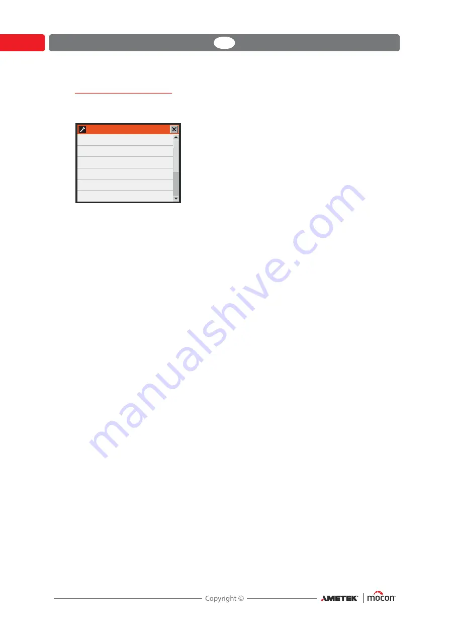
Buffer measure setup

Selecting 

Buffer measuring setup

 from the 

General setup 

menu will display a screen 

showing the setup parameters for the buffer measuring.

Measure on buffer

No

No automatic buffer measurement is performed.

Start up

An automatic buffer measurement is performed

when device is switched into measuring mode.

Always

An automatic buffer measurement is performed

when device is switched into measuring mode and

also when a new product is selected while in

measuring mode.

Allow manual

No

No manual measurement is allowed

measuring

When ready

A manual buffer measurement can only be started

when the device is in Ready mode.

Always

A manual buffer measurement can always be started.

Online measuring will be disabled while buffer

measurement runs.

Buffer measure time

The time that the device measures on the buffer tank. Ensure that 
the set time allows the gas to reach the sensor. A higher pressure and 
longer hose requires for a longer measuring time.

Hold Alarms

Yes

If a buffer measurement is above or below the set

O

2

%/CO

2

% limits, the alarm relay is activated and

remains activated until a new measurement has

been performed where the result is within the limits.

No

The alarm relay is activated for 4 secs.

Hold Warnings

Yes

If a buffer measurement is above or below the set

O

2

%/CO

2

% limits, the warning relay is activated and

remains activated until a new measurement has

been performed where the result is within the limits.

No

The warning relay is activated for 4 secs.

Buffer measure delay

(Parameter only appears when “External mixer connected” is set to 
“Yes” in the “external mixer settings” menu.)

Enter number of seconds to delay measuring after start of the buffer

pressure measurement.

The delay should ensure that the mixer has sufficient time to fill the 
buffer tank before measurement starts.

#VGGFSNFBTVSFTFUVQ

.FBTVSFPOCVGGFS

"MMPXNBOVBMNFBTVSJOH

#VGGFSNFBTVSFUJNF

)PME"MBSNT

)PME8BSOJOHT

#VGGFSNFBTVSFEFMBZ

/P

"MXBZT

TFD

/P

/P

TFD

Summary of Contents for AMETEK Dansensor MAP Check 3 Vacuum

Page 1: ...P N 320598 G 11 2019 UserGuide 7BDVVN...

Page 2: ...This blank page has been inserted to enable double sided printing of the document...

Page 3: ...ensor MAP Check 3 Vacuum EN User Guide P N 320598 G 11 2019 UserGuide Published by MOCON Europe A S R nnedevej 18 4100 Ringsted Denmark Tel 45 57 66 00 88 info dk mocon ametek com www dansensor com 7B...

Page 4: ...2 User Guide EN Dansensor MAP Check 3 Vacuum P N 320598 G 11 2019...

Page 5: ...nstallation 9 Operation and Maintenance 9 2 Introduction 11 Dansensor MAP Check 3 Vacuum 11 Flow System 13 Buffer version 14 No vacuum in the packaging machine 14 Overview 15 Gas connections 17 3 Conn...

Page 6: ...45 General 45 Spare parts 45 Cleaning 45 Replacing filter in the sample gas probe 45 Replacing buffer gas filter 46 Replacing air inlet filter 46 Replacing air inlet and outlet dust filters 47 Test mo...

Page 7: ...onfiguration and Use 75 Initial configuration 75 Using PuTTY 78 7 Technical Information 83 Technical specifications 83 Electrical connections 83 Mechanical data 83 Connectivity 83 Gas connection 84 Ba...

Page 8: ...6 User Guide EN Dansensor MAP Check 3 Vacuum P N 320598 G 11 2019...

Page 9: ...available at the time of publication Any differences between this manual and the equipment reflect improvements introduced after the publication of the manual Changes technical inaccuracies and typogr...

Page 10: ...r act according to the information in order to obtain the best possible function of the equipment CAUTION The operator must observe and or act according to the information in order to avoid any mechan...

Page 11: ...se install equipment as described in this manual Never install the equipment in explosive environments Always use correct fittings when connecting gas from the gas bottle Provide adequate space around...

Page 12: ...10 User Guide EN Dansensor MAP Check 3 Vacuum P N 320598 G 11 2019...

Page 13: ...f oxygen and carbon dioxide in the packaging process by observing critical points in the machine gas concentration at die and if used also quality of the buffer tank contents before start The device h...

Page 14: ...cost effective automated machine control The Black Box version can only be controlled from the packaging machine or a connected PC Fig 1 Dansensor MAP Check 3 Vacuum Black Box and Stand Alone devices...

Page 15: ...VE VACUUM GAS BUFFER V2 V1 VACUUM CAL GAS INLET AIR INLET SAMPLE LOOP SAMPLE GAS INLET O2 sensor Zr P1 V3 75 ml min 5 l min sample boost sample boost V4 P2 DIE Packaging Machine EVACUATION VALVE GASSI...

Page 16: ...hose that is used and the higher pressure the longer it will take to get the correct gas to the sensors Therefore make the hose as short as possible Do a test measurement to find out how long time it...

Page 17: ...stick Stand Alone versions only The connector is fitted with a water proof cover All versions have a USB connector on the backside of the device as well ON Status indicator Black Box versions only Wh...

Page 18: ...machine or external data collection via PC software SDK PSIP COM2 RS232 port D SUB 9 for control of MAP Mix Provectus gas mixer and for connection to terminal server for configuration Black Box LAN Et...

Page 19: ...PLE GAS INLET Connector for sample gas from packaging machine die AIR INLET For pressure equalisation with atmospheric air or for exhaust of bypass flow when measuring on the buffer tank and when cali...

Page 20: ...18 User Guide EN Dansensor MAP Check 3 Vacuum P N 320598 G 11 2019...

Page 21: ...320598 G 11 2019 3 Connections Gas Connections Correct mounting dismounting of fittings CAUTION When mounting dismounting fittings it is very important that you hold against on the already mounted fi...

Page 22: ...he other end to the packaging machine s vacuum system using the 1 4 RG hose fitting and the nylon gasket On Buffer versions connect the supplied buffer gas hose to the BUFFER GAS INLET inlet connector...

Page 23: ...ting pliers Connect the long hose to the device s sample gas inlet Connect the other end to the packaging machine s sample gas outlet using the delivered 1 8 RG hose fitting and the nylon gasket CAUTI...

Page 24: ...to make the connection but we recommend any of the methods described below Sample hose 3m with quick connector The hose can be shortened if required Male quick connector M5 Nylon gasket T fitting not...

Page 25: ...port on the packaging machine see I O signals for machine control on page 27 for details This cable is not delivered with the device Connect a 9 pole serial cable from the COM2 connector to the COM1...

Page 26: ...achine has the following pin connections Pins Colours Function Description 1 White 2 Brown GAS Gassing signal from packaging machine Signal levels 10 32 VDC bipolar Load max 10mA Must be activated dur...

Page 27: ...WARNING NO Warning relay output Activated if product or buffer alarm limit for O2 CO2 is exceeded Relay contacts max 48 VDC VAC Load max 1A Normally Open NO Contacts closed during power OFF 8 Red 10 P...

Page 28: ...or heating DSUB 25 pins colours Pin 11 Grey Pink Common Pin 12 Blue Red Pin 13 White Green ALARM Relay State of device Device OFF DSUB pin 5 connected to pin 6 Alarm OFF Device ON OK DSUB pin 5 connec...

Page 29: ...e I O Cable SIMPLE INSTALLATION FULL INSTALLATION Uses only ALARM signal to control the packaging machine Uses all signals to control the packaging machine 1 1 White White 2 2 Brown Brown 3 3 Green Gr...

Page 30: ...Isolationsbarriere Isolation barrier Isolationsbarriere Barri re d isolation Barri re d isolation Bipolar input 10 32 VDC 10 A max Bipolar input 10 32 VDC 10 A max Bipolar Eingang 10 32 VDC 10 A max...

Page 31: ...2 communication port DTE Male Pins text Description 2 RxD Receive data serial data input from packaging machine PLC 3 TxD Transmit data serial data output to packaging machine PLC 5 GND Ground signal...

Page 32: ...set External mixer connected to Yes This will fold out the gas configuration parameters Make appropriate settings 2 The product s must be setup with External mixer to Yes and then the appropriate sett...

Page 33: ...the various control options for the Dansensor MAP Check 3 Vacuum Use the PuTTY Terminal Server program for device configuration It can be used with all models but especially applies to the Black Box...

Page 34: ...een steady and the device is now ready for use Display models When first powered ON the display will shortly show the Dansensor MAP Check 3 Vacuum splash screen After a short internal self diagnosis t...

Page 35: ...period has finished the display will say Ready and the device is now ready for use If device is set up to perform buffer measurements the Buffer window is displayed in the lower right corner of the d...

Page 36: ...ishes It is recommended is to leave the device in measure mode so that it starts automatically Alternatively the measuring can be started and stopped manually using the Measure Stop key in the measuri...

Page 37: ...key Takes you to the Products list for selection of product See Selecting a product for measuring on page 36 for details Menu key Takes you to the Main menu See Main menu on page 53 for details Measu...

Page 38: ...t then press product to select it and return to the measuring screen If you have a very long list of products you can locate the product by pressing the Find key This will bring up the Find products s...

Page 39: ...arting with Sausages 8 Press the appropriate product to select it and return to the measuring screen TIP When selecting the Product name search method keying in only an S will bring up a list of all p...

Page 40: ...ported to a Service Technician to correct any errors See the complete Error Warning list on page 39 A list of the most recent errors warnings is available from the Diagnostics menu see Diagnostics men...

Page 41: ...e 8 Warning Error adding product product with this name already exists User information 9 Warning Product corrupt replaced with default parameters User information 10 Error No such product found Conta...

Page 42: ...e 38 Error External analog digital converter failed Contact service 39 Warning Atmospheric pressure sensor is not calibrated Pressure values may not be valid Contact service 40 Warning Difference pres...

Page 43: ...ges User information 70 Error Illegal mixer setting a 2 gas mixer is connected but 3 gas mixer is expected User information 71 Error Cannot establish connection to external mixer User information 72 E...

Page 44: ...88 Error Device temperature too high Check cooling filters If error persist contact service 89 Error Zr O2 cold junction temperature too low shutting down O2 sensor Check ambient temperature must be w...

Page 45: ...heck cooling filters If problem persists contact service 98 Error Input pressure too high Reduce pressure at gas input 99 Error Input pressure too low Increasepressure at gas input 101 Warning Product...

Page 46: ...ow Check flow system hoses 238 Error O2 reading is out of range 19 9 21 9 Check flow system hoses 239 Error Cannot reach Leak test pressure Checkleaktarget setting or vacuum supply 240 Error Connect c...

Page 47: ...t of spare parts see Spare parts consumables and accessories on page 87 Cleaning All of the device s surfaces should only be cleaned using a mild soap solution and a wrung cloth CAUTION Never use hard...

Page 48: ...ffer gas filter Buffer versions only Disconnect the gas inlet hose from the push in fitting Unscrew the push in fitting Replace the filter Connect fitting and hose again Replacing air inlet filter Uns...

Page 49: ...ly especially when device is used in a dusty environment To replace the air filters do the following Release the ventilation grille TIP If grille does not come off easily you can use a screwdriver or...

Page 50: ...um to the device and stop the packaging machine Enter Diagnostics and go to page 2 and select Test measuring Cal inlet in the menu The device starts a continuous measurement of the connected calibrati...

Page 51: ...iagnostics and go to page 2 and select Test measuring Buffer inlet in the menu The device starts a continuous measurement of the buffer tank gas It is now possible to close the Diagnostics window and...

Page 52: ...done periodically or in case of strange readings Apply vacuum to the device and stop the packaging machine Enter Diagnostics and go to page 2 and select System leak test in the menu A popup window wil...

Page 53: ...98 G 11 2019 In case of good result the following screen is shown In case of a failed result the following screen is shown NOTE Devices with CO2 sensor installed will have separate results for this se...

Page 54: ...52 User Guide EN Dansensor MAP Check 3 Vacuum P N 320598 G 11 2019...

Page 55: ...and delete products Display and delete logged product data See Product menu on page 54 for details Data log View logged data for currently selected product See Data log on page 58 for details Diagnost...

Page 56: ...on allows you to edit the setup of a product The following parameters can be set for each product Product name A unique product name of up to 40 characters Product number A unique product number 0 to...

Page 57: ...ill result in a relay activated accordingly and an indication in the display Buffer alarm settings Setting of buffer measurement warning and alarm values Buffer pressure is measured at every EVAC sign...

Page 58: ...ure bar Use gases from General Setup Yes or No O2 ratio O2 setting for mixer CO2 ratio CO2 setting for mixer N2 ratio N2 setting for mixer AUX ratio AUX setting for mixer Total flow Set the mixer outl...

Page 59: ...r the currently selected product only Delete collected data Use function to delete the logged data for an existing product The action must be confirmed before the data is deleted Delete all collected...

Page 60: ...e 54 for details Data logging parameters are set in General setup see page 60 for details Data log memory full If data log memory is full an error will occur Warning 23 see Error Warning list on page...

Page 61: ...perature the pressure in the sensors the sensor s conditions serial numbers for main components day hour counters time to calibration and software versions etc The parameters can only be read and not...

Page 62: ...packaging machine even though an error exists in the device This setting will be indicated in the measure screen by a warning symbol and a red text saying Faults disabled External mixer settings Opens...

Page 63: ...page 69 for details Supervisor PIN code setup Setting up the four digit PIN code required for changing from User access level to Supervisor access level See Access level on page 70 for details Extern...

Page 64: ...hat the set time allows the gas to reach the sensor A higher pressure and longer hose requires for a longer measuring time Hold Alarms Yes If a buffer measurement is above or below the set O2 CO2 limi...

Page 65: ...Log last values Set number of log entries in the data log ring buffer Only appears when Logging mode is set to Last values Network logging Select whether or not network logging is required No No netwo...

Page 66: ...ve Acknowledge Acknowledge byte can be used if a handshake is required for each measurement between device and server each to be set up to same value Disable network Select whether or not network erro...

Page 67: ...on Text Cycle counter Int Product name Text Product number Int Product barcode Text Timestamp Time yyyy MM dd HH mm ss O2 measurement Float O2 alarm state Text High Low O2 warning state Text High Low...

Page 68: ...low Float 0 00 O2 alarm limit high Float 0 00 O2 warning limit low Float 0 00 O2 warning limit high Float 0 00 CO2 measurement Float 0 00 CO2 alarm state Text Inactive High Low CO2 warning state Text...

Page 69: ...high Float 0 00 Buffer pressure Float 0 00 Buffer pressure alarm state Text Inactive High Low Buffer pressure warning state Text Inactive High Low Buffer pressure alarm limit low Float 0 00 Buffer pre...

Page 70: ...ation manually IP address Subnet mask Default gateway NOTE Always consult your network administrator before making network settings as incorrect settings can result in reduced or no network activity U...

Page 71: ...MM DD YY Time Date and Date format are related to the real time clock setting in the device The settings will have effect in all displays showing time and date Time format Setting of time format 12h o...

Page 72: ...000 After pressing OK you will be returned to the Main menu now displaying the additional menus for the Supervisor access level For best safety and correct operation of device you can easily return th...

Page 73: ...up screen PIN code has successfully been changed NOTE Make sure to note the new supervisor code in a safe location If you loose this information please contact your local Dansensor service department...

Page 74: ...collections Exports all data logs as text files stored on the device Export all products Exports the product database binary file stored on the device Import all products Imports the product database...

Page 75: ...Language Selecting Language from the Main menu will display a screen listing the available languages When selecting a language all text throughout the menus will be displayed in this language Select l...

Page 76: ...74 User Guide EN Dansensor MAP Check 3 Vacuum P N 320598 G 11 2019...

Page 77: ...uld install it from here to the computer from where you wish to connect to the device To do so insert the CD in your computer wait for the application to start and then follow the directions Preparati...

Page 78: ...mber of your computer s COM port to which the device is connected In the Speed field type 115200 2 Select the Keyboard entry in the Category list 3 Select VT100 item 4 Select Serial entry from the Cat...

Page 79: ...7 P N 320598 G 11 2019 7 To save the current setting we recommend that you give the session a name ex MC 3 Vac and click Save The next time you start the program you can easily retrieve the settings b...

Page 80: ...e Main menu Generally you use the arrow keys to navigate through the various menus and the Enter key to enter submenus change settings and or confirm a selection When entering figures either for acces...

Page 81: ...Dansensor MAP Check 3 Vacuum EN User Guide 79 P N 320598 G 11 2019 To do so select Change access level item and press Enter...

Page 82: ...ss level has been changed to supervisor The access code can be changed to one of your own selection using the Change administrator password function To return the device to user level access select Lo...

Page 83: ...se see General setup on page 60 To disable the connection to the device select Close terminal server from the Main menu and then press Enter to confirm This will end the session and return the device...

Page 84: ...82 User Guide EN Dansensor MAP Check 3 Vacuum P N 320598 G 11 2019...

Page 85: ...yser size 192 x 230 x 375 mm H x W x D Analyser weight 8 5 9 5 kg depending on model Box of one analyser 379 x 357 x 523 mm H x W x D Boxed weight 10 5 to 11 5 kg depending on model IP classification...

Page 86: ...ing ranges 0 100 O2 and optionally 0 100 CO2 Ambient temperature Operational 0 to 45 C less than 95 RH non condensing Storage 10 C to 60 C less than 95 RH non condensing Ambient pressure Operational 9...

Page 87: ...ion Zirconia sensor resolution 0 1 absolute in range above 10 0 01 absolute in range above 1 0 001 absolute in range below 1 Zirconia sensor accuracy 0 01 absolute in range below 0 01 3 0 001 absolute...

Page 88: ...N2 Ambient temperature 25 C 5 C Ambient relative humidity 35 65 RH Ambient pressure 1013 hPa 50 hPa Total calibration accuracy RMS 25 ppm 4 of reading in the range 1000ppm 100 Specification conditions...

Page 89: ...it multiplum filter fan 10 pcs ser cpl P N 301093 Filter 5 m 2 pcs ser cpl 1 P N 310629 Sampling kit on line pressure quick connector ser cpl P N 310630 Filter sample gas 0 2 2 pcs ser cpl P N 320722...

Page 90: ...O O O O Heater Unit O O O O O O Pump O O O O O O Fan unit O O O O O O Internal valve blocks O O O O O O Mounting hardware screws studs O O O O O O Internal cables O O O O O O Sample hose kit O O O O...

Page 91: ...This blank page has been inserted to enable double sided printing of the document...

Page 92: ...MOCON Europe A S R nnedevej 18 4100 Ringsted Denmark Tel 45 57 66 00 88 info com dk mocon ametek www dansensor com...

Reviews: