REPLACEMENT OF MAIN PCB ASSY
5
When replacing the MAIN PCB ASSY, write the LAMP TIME
memorized in the old MAIN PCB ASSY into a new MAIN
PCB ASSY.
Two methods are available to write the LAMP TIME. One is
to write the LAMP TIME only, and the other is to write the
whole data.
Necessary equipment
• Projector
• Personal computer (PC)
• RS-232C cable (attachment)
• program “change_main pcb” (only when writing WHOLE
DATA)
How to write the LAMP TIME
1. Before replacement
1) Make sure that the projector and the PC are turned off.
2) Connect the RS-232C terminal of the projector with the
COM terminal of the PC by the attached RS-232C cable.
3) Turn on the main power switch of the projector.
4) Turn on the PC and open the Hyper Terminal window.
(Refer to “Hyper Terminal Setting” of “Adjustment with
Microsoft
®
Windows
®
95 Operating System” for the
Hyper Terminal.)
5) When “00¯l
(
*
1)
” (command to display the LAMP TIME) is
entered on the Hyper Terminal window, the LAMP TIME
is returned as a return command and displayed on the
Hyper Terminal window. Here, write down the
underlined part of a return command as shown below.
(
*
1)
: “l” of “00¯l” is a small L.
[Ex.] 00¯l000217 : showing 2 hours and 17 minutes.
[Ex.] 00¯l050000 : showing 500 hours.
6) Turn of the main power switch and replace the MAIN
PCB ASSY.
2. After replacement
7) Open the Hyper Terminal window following the above
steps 2) to 4).
8) Enter the figure that you have written down at step 5) on
the Hyper Terminal window.
[Ex.] Enter “00¯l000217” when the written figure is 000217.
Make sure that “00¯l000217” is displayed on the
Hyper Terminal window as a return command.
[Ex.] Enter “00¯l050000” when the written figure is 050000.
Make sure that “00¯l050000” is displayed on the
Hyper Terminal window as a return command.
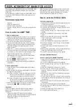
9) Check the LAMP TIME using the service command (by
pressing the “
”, “
” and “ENTER” buttons).
Important
Check the following when the Hyper Terminal window
doesn’t function correctly or a return command isn’t
displayed).
• Check the setting of the Hyper Terminal window
referring to “Hyper Terminal Setting” of “Adjustment with
Microsoft
®
Windows
®
95 Operating System”.
• Repeat from step 1).
When the Hyper Terminal window functions correctly and
the projector and the PC communicate normally, a return
command from the projector is displayed on the Hyper
Terminal window by entering “00¯l” at step 5).
How to write the WHOLE DATA
1. Before replacement
1) Connect the RS-232C terminal of the projector with the
COM terminal of the PC.
2) Turn on the main power switch of the projector.
3) Turn on the PC and copy the “change_main pcb” to the
desktop window of the PC.
4) Click the “pwb_change” icon. Open the Hyper terminal
window.
5) Click the “TRANSFER” and select the “CAPTURE
TEXT”.
6) Write the file name (EX : test.txt) in the “CAPTURE
TEXT” window and click the start button.
(Start the recording)
7) Click the “TRANSFER” and select the “SEND TEXT”.
8) Select the “read data” in the “change_main pcb” folder
and click the “OPEN”.
9) The PC send “read data” file to the projector. (2 or 3
minutes)
10) After the PC send the data, click the “TRANSFER” and
select the “CAPTURE TEXT” and “STOP”.
11) Turn off the main switch power of the projector.
2. Replace MAIN PCB ASSY
3. After replacing the MAIN PCB ASSY.
1) Connect the RS-232C terminal of the projector with the
COM terminal of the PC.
2) Turn on the main power switch of the projector.
3) Click the “pwb_change” icon. Open the Hyper terminal
window.
4) Click the “TRANSFER” and select the “test.txt”.
5) The PC send the “test.txt” of you recording to the
projector. (Write the some data to the memory of the
projector.)
6) After the PC send it, Click the “TRANSFER” and select
the “AD_gain_clamp.txt”.
7) The PC send the “AD_gain_clamp.txt” of you recording
to the projector. (Write the some data to the memory of
the projector.)
8) After the PC send it, Turn off the main switch power of
the projector.
9) Turn on the main power switch of the projector.
10) Press [menu] and [-], [ENTER] buttons on the projector
at the same time.
11) Confirm the lamp time on the service menu.
12) Turn off the main switch power.
Summary of Contents for S290U
Page 83: ...16 ...
Page 180: ...113 SYMBOL NO ADDRESS X7A1 A 3 PCB MAIN COMPONENT SIDE ...
Page 188: ...121 ...

