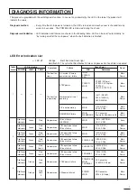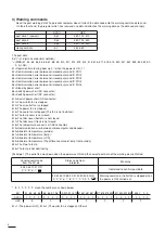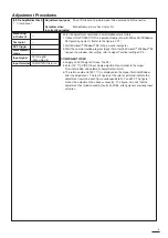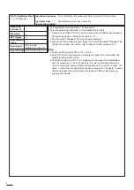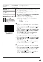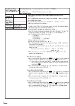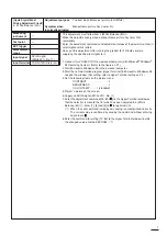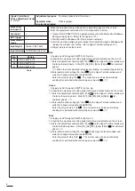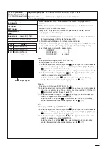
This product is provided with the self-diagnosis function. In case of any abnormality, the LED at the top of the product will
indicate the errors.
Diagnosis method
:
Every time the main power is turned on, the SW is turned on and each sensor is checked for any
errors in 4 seconds. The POWER LED remains red during the check.
Diagnosis result indication :
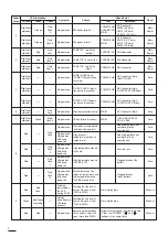
LED indication and failures are shown in the following table. LED can be reset “automatically” or
“by turning on/off of the main power” when the fault detection is finished.
---
: LED off
Orange
: Both Red and Green light
Red flash N : The cycle that Red flashes N times and goes out for fixed time is repeated.
DIAGNOSIS INFORMATION
Preferen-
tial order
1
Symptom
The front fan
stops.
The front fan
is operating.
No power-on
Failure
AC system (Primary
power source) failure
STBY power
Microcomputer is not
operating
PI0 is not operating
Main
Power
Main
Power
Main
Power
Main
Power
POWER
MAIN
INLET
POWER
PFC
MAIN
MAIN
STBY5 (SD 2pin),
STBY3.3 (SD 6pin or
TPST3.3),
STBY2.5 (TPST2.5)
IC417 (RESET),
X403 (100MHz),
X402 (40MHz)
IC7A0 (PIO0)
SCL3, SDA3
MEMBRANE failure
Main
Power
MAIN
MENBRANE
ST Connector,
Replace the Membrane switch
IIC bus failure
(EEPROM)
Auto
MAIN
IC414 (EEPROM)
SCL1, SDA1
Reset
Check Point
PCB
Reference
LED Indication
POWER
---
---
---
2
Red/Green
alternately
Green
Red
No power-on
PI01 operation failure
IIC bus failure
Main
Power
MAIN
IC7A2 (PIO1)
SCL3, SDA3
Red/Green
alternately
Green
Red
flash
No power-on
PI02 operation failure
IIC bus failure
Main
Power
MAIN
IC7A3 (PIO2)
SCL3, SDA3
Red/Green
alternately
Green
Red
flash 2
No power-on
PI03 operation failure
IIC bus failure
Main
Power
POWER SUB
IC9A5 (PIO3)
SCL3, SDA3
Red/Green
alternately
Green
Red
flash 3
No power-on
PI04 operation failure
IIC bus failure
Main
Power
AUDIO/MOTOR
IC9W0 (PIO4)
SCL3, SDA3
Red/Green
alternately
Green
Red
flash 4
No power-on
PI05 operation failure
IIC bus failure
Main
Power
TERMINAL
IC305 (PIO5)
SCL3, SDA3
Red/Green
alternately
Green
Red
flash 5
3
No power-on
STBY power failure
Main
Power
POWER SUB
MAIN
TERMINAL
SP Connector
STBYR5 (SP 6pin)
Red/Green
alternately
Orange
Red
flash
No power-on
SW power failure 3
Main
Power
POWER
MAIN
SD Connector
SW3.3 (SD 8pin)
Red/Green
alternately
Orange
Red
flash
2
LAMP
TEMP
LED Error Indication List
1
Summary of Contents for S290U
Page 83: ...16 ...
Page 180: ...113 SYMBOL NO ADDRESS X7A1 A 3 PCB MAIN COMPONENT SIDE ...
Page 188: ...121 ...

