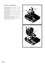
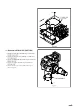
1
A
x5
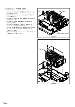
2
B
x6
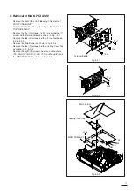
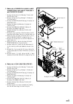
6
F
x4
7
G
x2
H
x1
8
I
x2
K
x4
J
x2
L
x2
9
!0
!1
!1
!2
!2
!4
!3
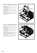
3
C
x1
D
x2
4
5
E
x3
O
x2
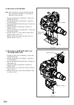
N
x1
!5
!6
M
x2
!7
!8
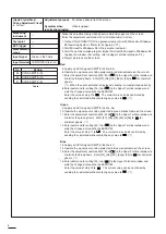
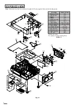
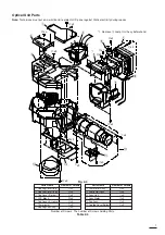
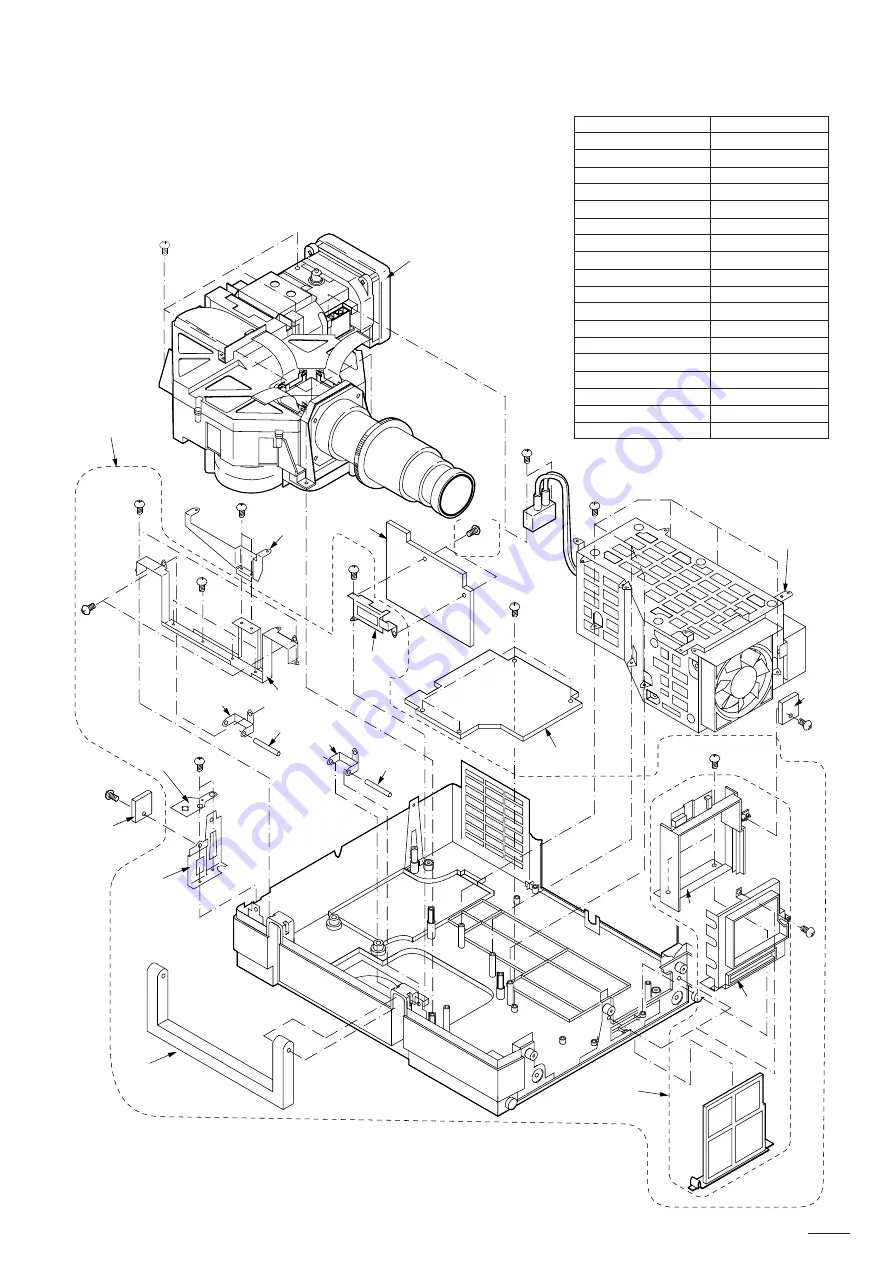
Note:
Technicians must put on a wrist band to protect LCD panel against Static electricity during repairs.
Number of Screws :
The number of Screws holding Parts.
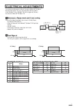
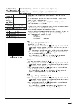
Table 2-2
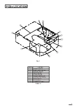
Fig. 2-2
5
Parts Name
Number of Screws
q
Optical Unit
A
x5,
O
x2
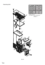
w
Power Assy
B
x6
e
PREAMP PCB ASSY
C
x1
r
Filter Base Assy
D
x2
t
Filter Duct
E
x3
y
POWER SUB PCB ASSY
F
x4
u
AUDIO/MOTOR PCB ASSY
none
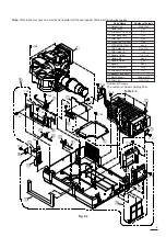
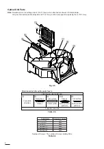
i
PCB Holder B
G
x2,
H
x1
o
PCB Holder A
I
x2
!0
Handle Holder
J
x2,
K
x4
!1
Handle Pin
none
!2
Handle Guide
L
x2
!3
Handle
none
!4
Case R Bracket
M
x2
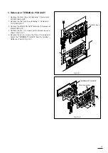
!5
PREAMP PCB ASSY
N
x1
!6
Bottom Case Assy
!7
Boss Support
Fixed with
!4
!8
Filter Unit
D
x2,
E
x3
Summary of Contents for S290U
Page 83: ...16 ...
Page 180: ...113 SYMBOL NO ADDRESS X7A1 A 3 PCB MAIN COMPONENT SIDE ...
Page 188: ...121 ...