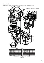
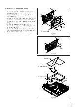
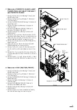
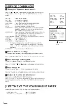
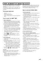
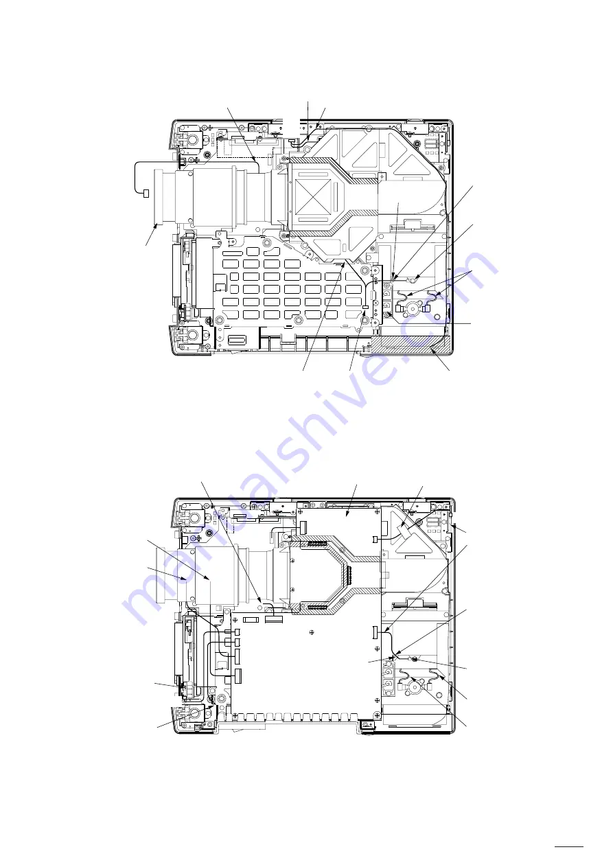
Fig. 4-2
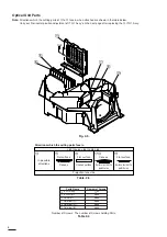
Fig. 4-3
NM
MH
MK
SC
NC
ST
SD
SM
SA
SF
SP
SZ
SL
AM
AL
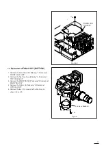
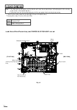
Lead dress When MAIN PCB ASSY is set
to MH
to MK
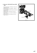
Optical Unit
from the fan
from NP of POWER
SUB PCB ASSY
PREAMP PCB ASSY
from NF of POWER
SUB PCB ASSY
from CN2 of Power Assy
from RD of Power Assy
MAIN PCB ASSY
PREAMP PCB ASSY
Brown Lead
Red Lead
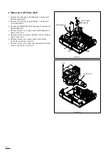
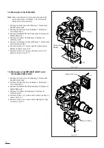
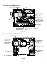
Lead dress When Optical Unit is set
from the fan under the Optical Unit
from the two thermistors
under the Optical Unit
to SZ of MAIN PCB
ASSY.
21
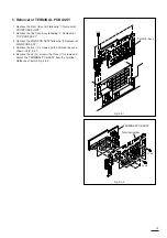
Do not cover the hole
A with the lead wires
(brown and red) of the
thermostat.
Do not bend the root
of the thermistor.
Keep the roots of the
lead wires (brown and
red) of the thermostat
bent as shown in the
figure.
Run the lamp
connector lead wire to
the fan’s side.
Put the slack of the
lead wire of the
thermistor into the gap
so that it doesn’t cover
the optical unit.
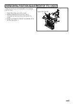
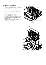
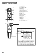
Do not cover the hole A
with the lead wires
(brown and red) of the
thermostat.
Do not bend the root of
the thermistor.
Hole A
Hole A
Tape
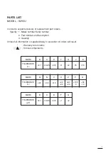
Summary of Contents for S290U
Page 83: ...16 ...
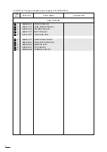
Page 180: ...113 SYMBOL NO ADDRESS X7A1 A 3 PCB MAIN COMPONENT SIDE ...
Page 188: ...121 ...


