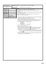
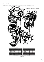
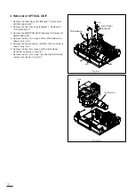
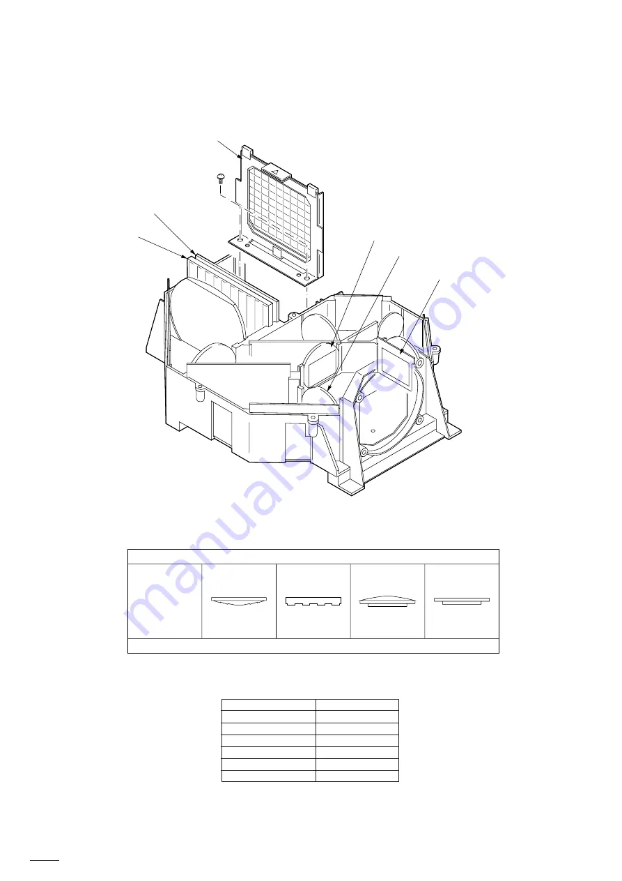
N
x2
!4
!5
!6
!7
!8
!9
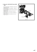
Note:
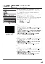
Directions which the setting parts of
!4
to
!9
face in when attached are shown in the table below.
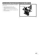
Carry out “Horizontal position adjustment of ITG 1 Assy” on the next page after replacing the
!4
ITG 1 Assy.
Number of Screws : The number of Screws holding Parts.
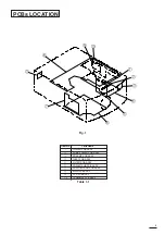
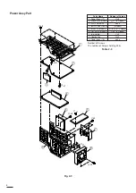
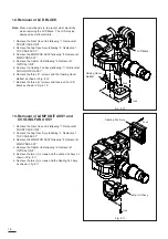
Table 2-6
Optical Unit Parts
Parts Name
Number of Screws
!4
ITG 1 Assy
N
x2
!5
ITG 2 Unit
none
!6
PBS Unit
none
!7
Polarizer (G)
none
!8
Polarizer (R)
none
!9
Polarizer (B)
none
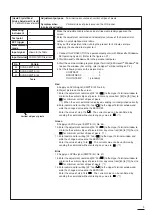
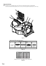
Fig. 2-5
Table. 2-5
!4
!5
!6
!7!8
!9
8
Light source side (Lamp side)
In possible
directions
Flat surface
Flat surface
Flat surface
Uneven surface
Convex
Convex
Surface to stick the
polarizer on
Surface to stick the
polarizer on
Directions which the setting parts face in
Projection lens side
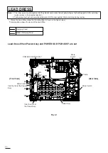
Summary of Contents for S290U
Page 83: ...16 ...
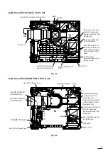
Page 180: ...113 SYMBOL NO ADDRESS X7A1 A 3 PCB MAIN COMPONENT SIDE ...
Page 188: ...121 ...