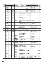
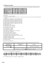
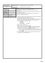

Adjustment purpose
[Liquid Crystal Panel
Driving Adjustment Circuit]
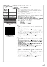
5. White Balance (20%)
Symptom when
incorrectly adjusted
Measuring
instrument
Test point
EXT trigger
Measurement
range
Input signal
Input terminal
The best white balance of picture.(20%White)
Monochrome picture has a color tint.
---
---
---
---
SVGA signal
(White 20%, No. 11)
COMPUTER IN terminal
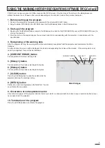
* This adjustment must follow item 4 (White Balance (50%)).
* Make this adjustment only when a monochrome picture has color tints
remarkably.
* Enter the adjustment commands and adjustment values of the decimal number in
small alphanumeric letters.
* Carry out this adjustment after running the product for 2 minutes or more
supplying the specified test signal to it.
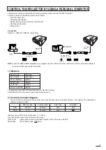
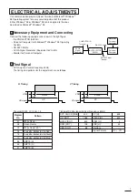
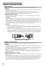
1. Connect this PROJECTOR to a personal computer (with Microsoft
Windows
95 Operating System). (Refer to the figure on P.1)
2. Start Microsoft
Windows
95 in the personal computer.
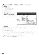
3. Start the communication program [Hyper Terminal] in Microsoft
Windows
95
to open the window. (For setting, refer to Hyper Terminal setting on P.2)
4. Set the following items on the picture menu.
CONTRAST . . . . . . . . . . . . . . .0
BRIGHTNESS . . . . . . . . . . . . .0
COLOR TEMP . . . . .1 (standard)
5. Project a picture on the screen.
6. Supply an SVGA signal (White 20%, No. 11).
7. Enter the adjustment command [00~822
] to the Hyper Terminal window so
that the color tint is close to the tint which has been adjusted in 4 (White
Balance (50%)). Enter [1], [3] and [4] to
for optimum tint.
(*1) When the sent command is displayed, sending is accomplished correctly.
The current value is confirmed by sending the command without entering
any value to
.
8. Enter the command for writing [00~83] to the Hyper Terminal window to write
the changed value onto the EEPROM. (*1)
7
Summary of Contents for S290U
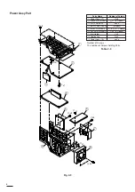
Page 83: ...16 ...
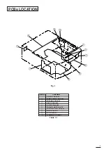
Page 180: ...113 SYMBOL NO ADDRESS X7A1 A 3 PCB MAIN COMPONENT SIDE ...
Page 188: ...121 ...