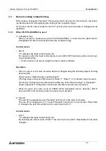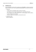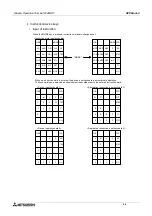
Graphic Operation Terminal F940GOT
HPP Mode 4
4-13
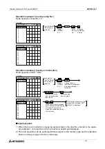
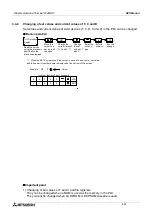
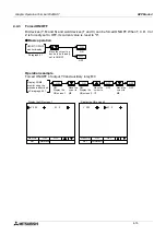
Operation example
Monitor of the ON/OFF status of inputs X000 and X001 and monitor of the current value and
the set value of timer T3
n
n
n
n
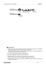
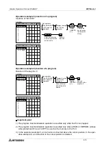
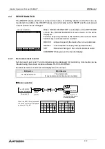
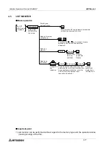
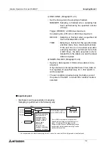
Important point
1) Monitor function when timers and counters are indirectly specified
If a data register is used for the set value of a timer/counter as
shown in the program on the left, the contents of the data register
is monitored as the set value of the timer/counter when monitoring
is performed.
When the set value is changed (as described on the next page),
the contents of the data register are overwritten.
Display the screen 1
X 000
T 3
X 001
CUR
SET
[ 1234]
[ 2345]
RST( )
Display the screen 2
SW1
TIM
SW2
CUR
SET
[ 1234]
[ 2345]
RST( )
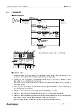
ON status
The ON/OFF status of each monitored
device is indicated as follows.
OFF status
The HPP
MODE screen
is displayed.
DEVICE MONITOR
Select "DEVICE
MONITOR" on the
screen.
DEVICE
Enter a device
symbol "X".
X
ENT
Select
"X0".
0
Display "X0"
on the screen.
DEVICE
Enter a device
symbol "T".
T
3
Select
"T3".
ENT
Display the
screen 1.
COMMENT
Display the
screen 2.
When a comment has been entered to a device, the
device is displayed with the comment.
When a comment has not been entered to a device,
the device is displayed with the symbol.
This comment display function is valid only when
comments have been created using the screen
creation software FX-PCS-DU/WIN-E.
Display "X1" on
the screen.
Paragraph 4.1
D5
D6
T10
C10
Summary of Contents for F940GOT-LWD-E
Page 1: ...OPERATION MANUAL F940GOT SWD E F940GOT LWD E...
Page 4: ...Graphic Operation Terminal F940GOT 2...
Page 6: ...Graphic Operation Terminal F940GOT 4...
Page 8: ...Graphic Operation Terminal F940GOT 6...
Page 14: ...Graphic Operation Terminal F940GOT Contents vi...
Page 104: ...Graphic Operation Terminal F940GOT Alarm Mode 6 6 12...
Page 148: ...Graphic Operation Terminal F940GOT Creation of Display Screens 9 9 30...
Page 228: ...Graphic Operation Terminal F940GOT Changeover of Display Screen FX PCS DU WIN E 11 11 18...

