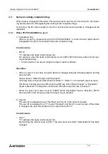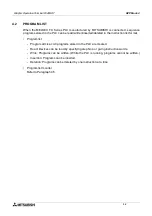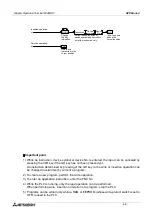
Screen Mode 3
3-1
3.
Screen Mode
This section describes the screen mode in which user screens are displayed.
Confirm the outline of and the operating procedures in the screen mode.
For the contents related to the screen design, refer to Sections 9 to 13.
3.1
Outline of screen mode
In the screen mode, screens created by the user using the screen creation software are dis-
played. In addition, alarm messages are displayed.
On one display screen, characters, straight lines, rectangles, circles, etc. which are classified
in accordance with their functions are combined and displayed.
When there are two or more user screens, they can be changed over using the operation keys
in the GOT or using the PLC. (The user can set arbitrarily the condition to change over the
screens and the screen to be displayed next.)
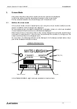
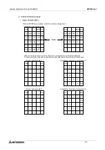
On one screen, the following elements can be displayed. (In the display example below, only a
part of the available functions are used.)
In the F940GOT-SWD-E, eight colors are available to create screens.
START
STOP
0:EMS
MITSUBISHI
Text
Straight line
Numeric
Bar graph
Rectangle
Indicator (reverse)
Time
Circle
F940GOT
13:26:05
56238
MONITOR
Examples of display screen
Graphic Operation Terminal F940GOT
Summary of Contents for F940GOT-LWD-E
Page 1: ...OPERATION MANUAL F940GOT SWD E F940GOT LWD E...
Page 4: ...Graphic Operation Terminal F940GOT 2...
Page 6: ...Graphic Operation Terminal F940GOT 4...
Page 8: ...Graphic Operation Terminal F940GOT 6...
Page 14: ...Graphic Operation Terminal F940GOT Contents vi...
Page 104: ...Graphic Operation Terminal F940GOT Alarm Mode 6 6 12...
Page 148: ...Graphic Operation Terminal F940GOT Creation of Display Screens 9 9 30...
Page 228: ...Graphic Operation Terminal F940GOT Changeover of Display Screen FX PCS DU WIN E 11 11 18...


