Graphic Operation Terminal F940GOT
Start up 2
2-9
2.3
Each mode selection procedure
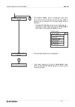
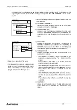
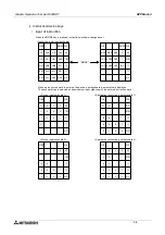
[ SELECT MODE ]
END
USER SCREEN MODE
ALARM MODE
HPP MODE
SAMPLING MODE
TEST MODE
OTHER MODE
MODE SELECT MENU SCREEN
Production control
Number of products
Operation rate
1234
[ HPP MODE ]
END
PROGRAM LIST
PARAMETER
[ SUMPLING MODE ]
END
SET CONDITION
DISPLAY LIST
[ ALARM MODE ]
END
DISPLAY STATUS
DISPLAY HISTORY
USER SCREEN MODE
HPP MODE
SUMPLING MODE
ALARM MODE
•
If "MAIN MENU CALL KEY" has been set in
"SET-UP MODE", when a specified touch key is
pressed, the SELECT MODE screen shown on
the left is displayed.
•
The outline of each mode and the selection pro-
cedure are described below.
•
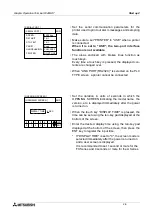
USER SCREEN MODE (Refer to
Sections 3, 9, 10, 11, 12 and 13.)
A user screen is displayed.
Characters such as standard text,
numerics, Katakana and Kanji and
simple graphic can be displayed.
•
HPP MODE (Refer to Section 4.)
List programs can be read/written/
monitored, and bit devices and
word devices in the PLC can be
monitored.
Set values of T, C and D can be
changed.
•
SAMPLING MODE
(Refer to Section 5.)
The current value of specified data
is acquired in a constant cycle or
when the trigger condition is satis-
fied.
•
ALARM MODE
(Refer to Section 6.)
Bit devices are monitored as alarm
e l e m e n t s . W h e n a b i t d ev i c e
becomes ON, a corresponding
message is displayed.
Summary of Contents for F940GOT-LWD-E
Page 1: ...OPERATION MANUAL F940GOT SWD E F940GOT LWD E...
Page 4: ...Graphic Operation Terminal F940GOT 2...
Page 6: ...Graphic Operation Terminal F940GOT 4...
Page 8: ...Graphic Operation Terminal F940GOT 6...
Page 14: ...Graphic Operation Terminal F940GOT Contents vi...
Page 104: ...Graphic Operation Terminal F940GOT Alarm Mode 6 6 12...
Page 148: ...Graphic Operation Terminal F940GOT Creation of Display Screens 9 9 30...
Page 228: ...Graphic Operation Terminal F940GOT Changeover of Display Screen FX PCS DU WIN E 11 11 18...

