


28
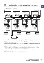
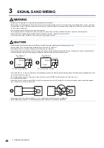
3 SIGNALS AND WIRING
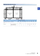
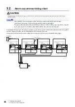
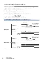
3.2 Alarm occurrence timing chart
■
Formula for calculating the rapid stop deceleration time
*1 In addition to [pulse/s], [mm/min], [inch/min], and [degree/min] are used for the control unit of the Motion controller. When a control unit
other than [pulse/s] is used, convert the unit into [pulse/s] to calculate the rapid stop deceleration time.
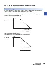
■
Setting example of the rapid stop deceleration time
Condition
Servo motor rated speed: 2000 [r/min] (Depends on the servo motor)
Speed limit value: 2097152 [pulse/s] (Depends on users, setting by the motion controller)
Forced stop deceleration time constant: 1000 [ms] (Depends on users, setting by the drive unit)
Therefore, set the rapid stop deceleration time of the motion controller to 1 ms.
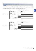
If an alarm subject to the forced stop deceleration function occurs
The following timing chart shows that an alarm occurs in any axis in the parallel drive system.
*1 The model speed command is a speed command generated in the servo amplifier for forced stop deceleration of the servo motor.
Rapid stop deceleration time [ms] =
Forced stop deceleration time constant [ms] × Speed limit value [pulse/s]
*1
× 60 [s]
Servo motor rated speed [r/min] × 4194304 [pulse]
Rapid stop deceleration time [ms] =
1000 × 2097152 × 60
2000 × 4194304
= 15 [ms]
The command from the
controller is not received.
The command from the
controller is not received.
Alarm occurrence
Alarm No.
No alarm
No alarm
Model speed command is 0,
and the speed is equal to
or less than zero speed
*1
ON (no alarm)
OFF (alarm)
Base circuit
(Energy supply to
the servo motor)
Base circuit
(Energy supply to
the servo motor)
ON
OFF
Drive unit display
0 r/min
Servo motor speed
ALM (Malfunction)
Model speed command is 0,
and the speed is equal to
or less than zero speed
*1
Alarm E7
ON (no alarm)
OFF (alarm)
ON
OFF
Drive unit display
0 r/min
Servo motor speed
ALM (Malfunction)
Alarm occurrence axis
Alarm non-occurrence axis
Summary of Contents for Melservo-J4 MR-J4-DU*B4-RJ100 Series
Page 2: ......
Page 75: ...9 USING STO FUNCTION 73 9 MEMO ...
Page 81: ...11 APPENDIX 11 1 Analog monitor 79 11 MEMO ...
Page 85: ......


