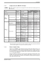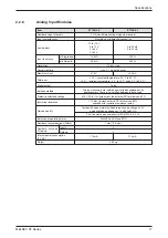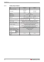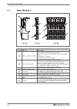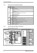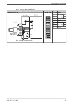
The
ST1PDD
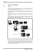
power feeding module supplies the connected actuators and sensors with a 24 V
direct current.
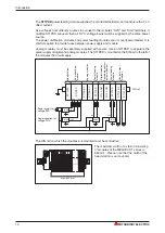
Use voltages from different sources to connect to the module’s “SYS” and “AUX” terminals. If
multiple ST1PSD are used, then all “SYS” voltage inputs must be supplied by the same power
source.
The power distribution modules and power feeding modules are not overload-protected. It is
strictly required to provide fuses between power supply and module.
Analog modules must be separately supplied with power. Use an ST1PDD to separate the
power supply of digital and analog modules. The ST1PDD is mounted on the DIN rail to the left of
the modules that it will supply.
The DIN rail on which the modules are mounted must be conductive.
Introduction
10
MITSUBISHI ELECTRIC
AC/DC
AC/DC
AC/DC
AC/DC
SYS.
AUX.
AUX.
AUX.
24 V
24 V
24 V
24 V
Head
station
Bus
refres
h
ing
moduel
Analog
modules
P
o
w
e
r
feeding
module
Digital
m
odules
(e
xcluding
contact
output
modules)
Contact
output
modules
DIN rail
P
o
w
e
r
feeding
module
Power supply for
voltage SYS
Power supplies for
voltage AUX
ST1H-PB
ST1PSD
ST1AD2-V
ST1DA2-V
ST1PDD
ST1PDD
ST1Y2-DE1
ST1X2-DE1
ST1Y2-R2
ST1Y2-R2
161
131
151
ST1X16
-DE1
RUN
ERR.
21
11
41
31
61
51
81
71
101
91
121
141
111
11
31
51
71
91
111
131
151
21
41
61
81
101
121
141
161
12
32
52
72
92
112
132
152
22
42
62
82
102
122
142
162
13
33
53
73
93
113
133
153
23
43
63
83
103
123
143
163
14
34
54
74
94
114
134
154
24
44
64
84
104
124
144
164
ST1X2
-DE1
RUN
ERR.
21
11
11
21
12
22
13
23
14
24
ST1PSD
RUN
ERR.
PW
11
11
21
21
12
12
22
22
13
14
13
14
23
24
23
24
MITSUBISHI
STATION
ST1H-PB
ON
RS-232C
RELEASE
RESET
PROFIBUS I/F
+
-
RUN
M 1
ERR.
M 2
REL.
DIA
SYN.
BF
FRE.
80
S
T
A
T
I
O
N
N
O
40
20
10
8
4
2
1
ST1DA2
-V
RUN
ERR.
11
21
12
22
13
23
14
24
ST1AD2
-I
RUN
ERR.
11
21
12
22
13
23
14
24
ST1AD2
-V
RUN
ERR.
11
21
12
22
13
23
14
24
The maximum width of a station consisting
of modules of the MELSEC ST series is
850 mm. Please note that the width of the
head station is not counted.
max. 850 mm

