4
Installation
4.1
Handling Instructions
Precautionary measures
Because the casings and the terminal cover are made of plastic, ensure that the modules are not
subjected to mechanical stresses or strong jolts. Under no circumstances may the circuit boards
be removed from the device. During the installation ensure that no wires or metal shavings pen-
etrate into the casing.
Tighten the terminal screws and the anchoring screw of the end plate to the torques specified in
the following table:
E
ATTENTION:
Do not open the module casing. Do not modify the module.
Malfunctions, injury and/or fire can result.
The ST modules are designed for mounting on a DIN rail. If the modules are not oper-
ated on a DIN rail, then malfunctions can occur.
4.2
Mounting the DIN Rail
쎲
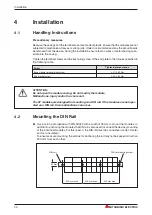
Use a rail in accordance with DIN 50022 with a width of 35 mm to mount the modules. In
addition to anchoring the modules the DIN rail is also used to connect the device grounding
of the individual modules. For this reason, the DIN rail must be conductive (made of metal
and non-insulated).
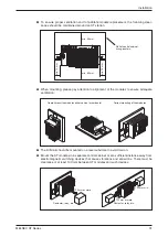
To ensure secure mounting, the screws for anchoring the rail may not be spaced more than
200 mm from each other:
Installation
30
MITSUBISHI ELECTRIC
Screw
Tightening torgue range
Base module terminal block screw
0.27–0.80 Nm
End bracket screw
0.50–0.60 Nm
200 mm max.
200 mm max.
200 mm max.
35 mm
DIN rail
DIN rail mounting screw

