5
Trouble Shooting
If you cannot communicate with the head station via PROFIBUS, or if all RUN LEDs of the mod-
ules are not illuminated, or if an ERR LED is switched on, then there is an error. Detailed instruc-
tions for trouble shooting and error resolution are included in the manuals of the individual
modules. The steps listed in this chapter are provided as a general guide for trouble shooting.
5.1
Checking the System Set-Up
When trouble shooting, first check the system set-up:
쎲
Is the correct number of ST modules connected to a head station?
A maximum of 63 modules (26 analog modules) can be connected to one head module.
For those modules that exceed this range, the RUN LED remains switched off.
쎲
Is the number of assigned I/O addresses within the permissible range?
A maximum 256 I/O addresses can be assigned by one ST station. If the permissible num-
ber is exceeded, then the RUN LED does not light up on the modules that are outside of the
range.
쎲
Are electronic modules plugged onto all base modules?
All electronics modules must be installed before switching on the supply voltage.
쎲
Are the electronics modules mounted on the correct base module?
There is an appropriate base module for each electronics module (see page 9). Check
whether the correct combination is used.
쎲
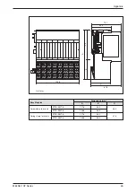
Is the system shorter than 85 cm?
The total width of the ST Module connected to a head module may not exceed 85 cm (see
page 9).
쎲
Is the power consumption of the modules within the capacity of the power supply?
It may be that the connected ST modules exceed the capacity of the internal 5 V supply.
The capacity of the 24 V supply can be exceeded by the ST modules and connected
devices. Instructions for calculating power consumption are included in the operating man-
ual of the ST modules.
5.2
Head Station Self-Diagnostics
This self-diagnostics check only the head station:
햲
Switch-off the supply voltage of the ST station:
햳
Unplug the plug of the PROFIBUS/DP line from the head station.
햴
Set the value “150” on the switches of the head station (see page ).
햵
Switch-off the supply voltage of the ST station: The self-diagnostics start automatically
and the LEDs “RUN” and “DIA” start flashing.
햶
After concluding the self diagnostics the LED “RUN” gives an indication of the result:
–
If the “RUN” LED is illuminated: No error was determined. Reset the switch setting on
the head station to the station number.
–
If the “RUN” LED is not lit up: Execute the self-diagnostics again. If the “RUN” LED is still
not illuminated, then there is a hardware error. Check the status of the LEDs “REL”,
“DIA” and “BF” and contact the MITSUBISHI service.
Trouble Shooting
MELSEC ST Series
41

