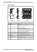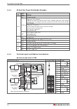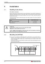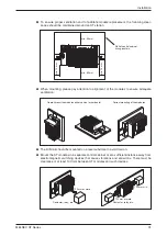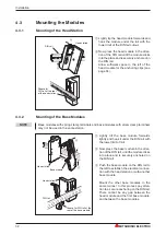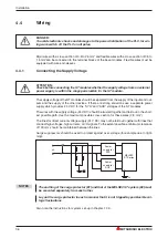
Mounting the Base Module Markers and Wiring Markers
Installation
MELSEC ST Series
33
Place the base module markers in the
apertures provided underneath the connec-
tion for an electronics module.
Base module
Base module
marker
The wiring is identified and diagnostics are
simplified with the colored wiring markers.
Color coding is listed in the following table.
Plug each wiring marker in the slots under-
neath the terminals.
Wiring marker
Base module
Colour of wiring marker
Meaning
Black
Signal wires
Red
Positive pole of a DC voltage (24 V DC, 5 V DC)
Blue
Positive pole of a DC voltage (24 V DC, 5 V DC)
N conductor of an AC voltage
Red/Blue
System power supply
Yellow/Green
Protective earth
Green
Shield
Brown
Phase of an AC voltage (L1)

