4.4.2
Connecting the I/O Signals
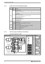
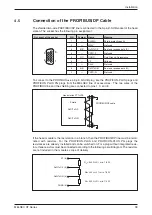
Assignment of base module terminal blocks is described in section 3.4.3.
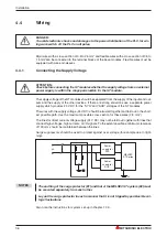
The lines to the inputs and outputs should always be laid out separately.
Use insulated lines, if the lines with input and output signals cannot be laid out at a sufficient dis-
tance from network lines, or from lines that conduct high currents. Analog signals should always
be connected via insulated lines. Connect the shielding of the line on one side to the terminals
provided on the MELSEC ST station. The terminals, ST1A-SLD-S (for spring clamp terminals)
and ST1A-SLD-E (for screw clamp terminals) are available for this purpose.
Metal conduit or cable channels that the wiring runs through, must be earthed.
Lines that conduct input or output signals (24 V DC) must be laid out separately from lines that
conduct alternating current 110 / 230 V).
NOTE
For line lengths over 200 m, capacity losses may occur which can corrupt the input signals.
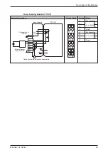
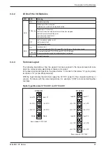
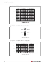
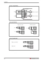
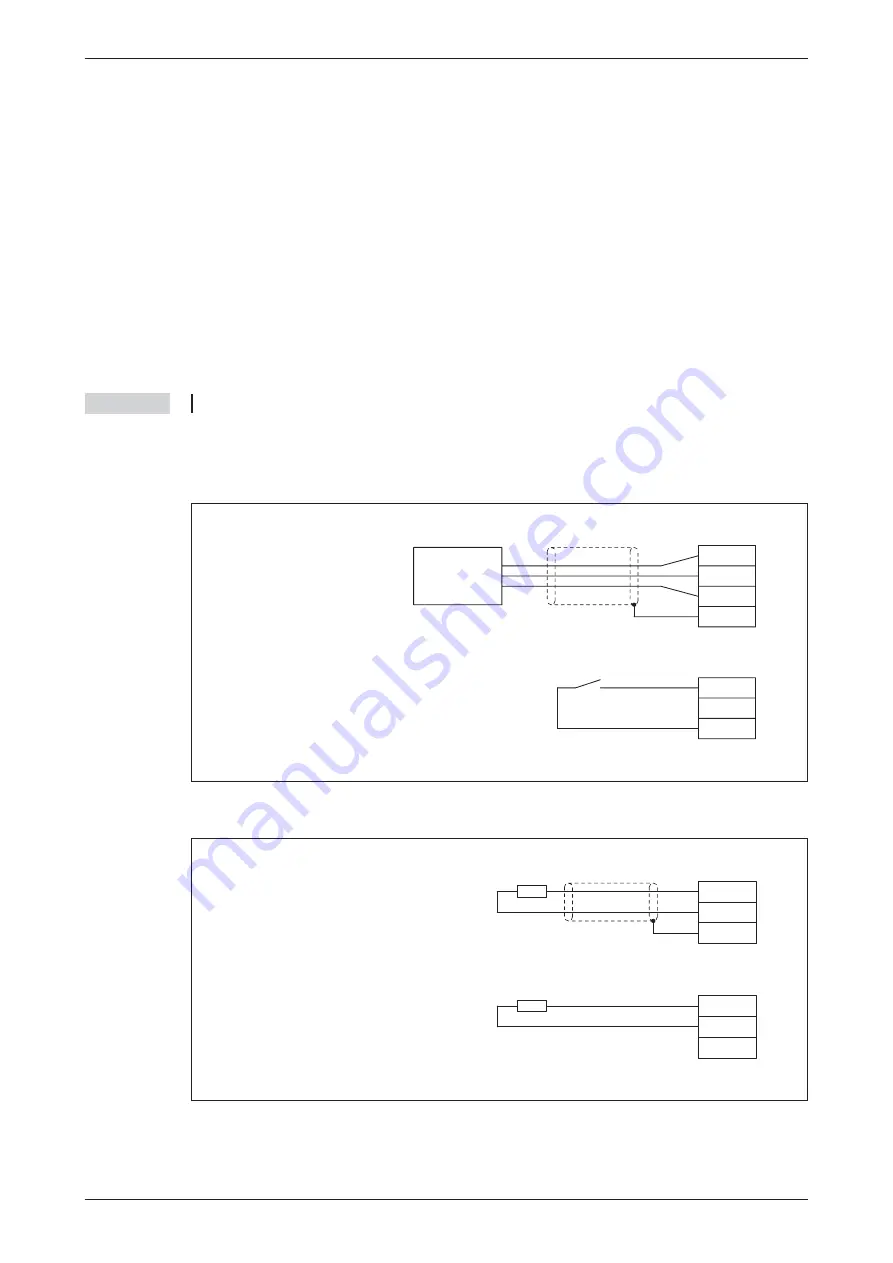
The following illustrations show the connection of the I/O signals.
Digital Input Modules
Transistor Output Modules (Source Type)
Installation
MELSEC ST Series
37
3-wire Sensor
Input
–24 V DC
+24 V DC
Shield
Input
–24 V DC
+24 V DC
Switch
Output
–24 V DC
Shield
Output
–24 V DC
Shield
External load, connected via a shielded cable
External load, connected via a non shielded cable


