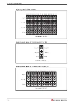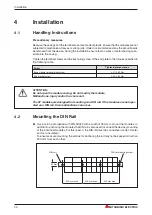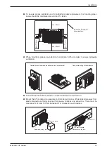
3
Description of the Modules
3.1
Head Station
3.1.1
Overview
Description of the Modules
MELSEC ST Series
19
MITSUBISHI
STATION
ST1H-PB
ON
RS-232C
RELEASE
RESET
PROFIBUS I/F
+
-
RUN
M 1
ERR.
M 0
REL.
DIA
SYN.
BF
FRE.
80
S
T
A
T
I
O
N
N
O
40
20
10
8
4
2
1
쐃
���
���
���
���
���
���
���
���
쐅
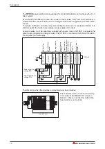
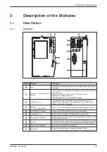
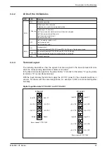
Number Meaning
Description
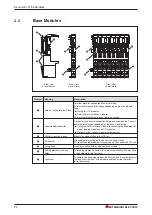
쐃
LEDs
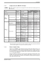
The LEDs show the operating status of the head station. (refer to the
next page)
쐇
Switches for setting the station
number
These switches are used to set the station number and to activate the
self-diagnostics.
Range for the station number: 0 to 99 (factory setting: 0)
Selection of self-diagnostics: 150
Refer to chapter 3.1.3 for a detailed description.
쐋
RS232 interface
For diagnostics and configuration a personal computer with the
software GX Configurator DP installed (version 6.0 or later) is con-
nected with this Mini-DIN socket.
쐏
Buttons
("-", "+" and "RELEASE")
Used to make online module change and to reset the head station..
쐄
PROFIBUS/DP interface
Connects the PROFIBUS/DP cable to the head module.
쐂
Display plate
Write the station number of the head station on this plate
쐆
Base module connector
Connects the next module (always a power distribution module) to the
right of the head station.
쐊
Lock lever
To remove the head station from the DIN rail, a screwdriver is inserted
in this lever from the front of the module and then pulled downward.
쐎
DIN rail mounting groove
Mounts the head station to the DIN rail.
쐅
FG contact
Grounding metal spring on the back of the head station.
FG of all mounted modules ist connected via the conductive DIN rail.

