4.5
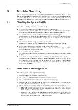
Connection of the PROFIBUS/DP Cable
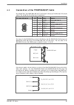
The shielded two-wire PROFIBUS/DP line is connected to the 9-pin D-SUB socket of the head
station. The socket has the following pin assignment:
To connect to the PROFIBUS use a 9-pin D-SUB plug like the PROFICON-PLUS plugs and
PROFICON PLUS PG plugs from the MELSEC line of accessories. The two wires of the
PROFIBUS line and the shielding are connected to pins 1, 3, and 8.
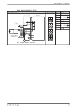
If the head module is the last station in a branch, then the PROFIBUS/DP line must be termi-
nated with resistors. For the PROFICON-PLUS and PROFICON-PLUS PG plugs the
resistances are already installed and can be switched on. For a plug without integrated resis-
tors, three resistors must be connected according to the following circuit diagram. The resistors
are not included in the module’s scope of delivery.
Installation
MELSEC ST Series
39
Pin Layout of the socket
PIN
Symbol
Name
Meaning
1
—
SHIELD
Shield, protective earth
2
—
M24V
Not used
3
B/B
쎾
RxD/TxD-P
Sent and received data (P)
4
—
CNTR-P
Not used
5
C/C
쎾
DGND
Data Ground, Datenmasse
6
—
VP
V
7
—
P24V
Not used
8
A/A
쎾
RxD/TxD-N
Sent and received data (N)
9
—
CNTR-N
Not used
1
3
8
PROFIBUS/DP cable
Head station ST1H-PB
Shield
RxD/TxD-P
RxD/TxD-N
VP (6)
RxD/TxD-P (3)
RxD/TxD-N (8)
DGND (5)
R
U
= 390
Ω ±
2%, min. 1/4 W
R
tA
= 220
Ω ±
2%, min. 1/4 W
R
d
= 390
Ω ±
2%, min. 1/4 W
5
1
9
6

