126
RS-48
5
communi
cat
ion
331
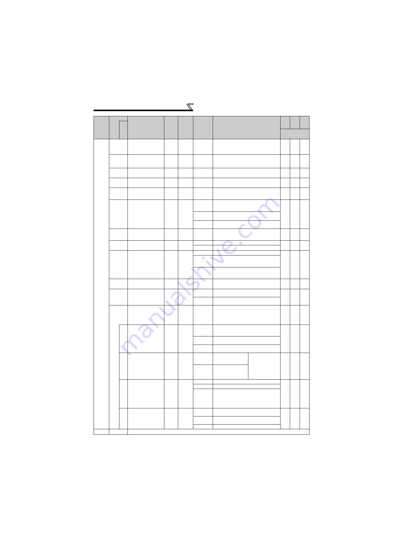
RS-485
communication
station number
1
0
0 to 31
(0 to 247)
Set the inverter station number.
(same specifications as
Pr. 117
) When "1"
(Modbus-RTU protocol) is set in
Pr. 551
, the
setting range within parenthesis is applied.
{
{
{
332
RS-485
communication speed
1
96
3, 6, 12,
24, 48, 96,
192, 384
Used to select the communication speed.
(same specifications as
Pr. 118
)
{
{
{
333
RS-485 communication
stop bit length
1
1
0, 1, 10, 11 Select stop bit length and data length. (same
specifications as
Pr. 119
)
{
{
{
334
RS-485 communication
parity check selection
1
2
0, 1, 2
Select the parity check specifications. (same
specifications as
Pr. 120
)
{
{
{
335
RS-485 communication
retry count
1
1
0 to 10,
9999
Set the permissible number of retries at
occurrence of a data receive error. (same
specifications as
Pr. 121
)
{
{
{
336
RS-485
communication
check time interval
0.1s
0s
0
RS-485 communication can be made, but the
inverter will come to trip in the NET operation
mode.
{
{
{
0.1 to
999.8s
Set the communication check time interval.
(same specifications as
Pr. 122
)
9999
No communication check
(signal loss detection)
337
RS-485 communication
waiting time setting
1
9999
0 to 150ms,
9999
Set the waiting time between data
transmission to the inverter and response.
(same specifications as
Pr. 123
)
{
{
{
338
Communication operation
command source
1
0
0
Operation command source communication
{
{
{
1
Operation command source external
339
Communication
speed command
source
1
0
0
Speed command source communication
{
{
{
1
Speed command source external (Frequency
setting from communication is invalid,
terminal 2 and 1 setting from external is valid)
2
Speed command source external (Frequency
setting from communication is valid, terminal
2 and 1 setting from external is invalid)
341
RS-485 communication
CR/LF selection
1
1
0, 1, 2
Select presence/absence of CR/LF. (same
specifications as
Pr. 124
)
{
{
{
342
Communication
EEPROM write
selection
1
0
0
Parameter values written by communication
are written to the EEPROM and RAM.
{
{
{
1
Parameter values written by communication
are written to the RAM.
343
Communication
error count
1
0
—
Displays the number of communication errors
during Modbus-RTU communication.
Read only.
Displayed only when Modbus-RTU protocol is
selected.
×
×
×
539
Modbus-RTU
communication
check time interval
0.1s
9999
0
Modbus-RTU communication can be made,
but the inverter will come to trip in the NET
operation mode.
{
{
{
0.1 to 999.8s Set the communication check time interval.
(same specifications as
Pr. 122
)
9999
No communication check (signal loss
detection)
549
Protocol selection
1
0
0
Mitsubishi inverter
(computer link)
protocol
After setting change,
reset (switch power
off, then on) the
inverter.
The setting change
is reflected after a
reset.
{
{
{
1
Modbus-RTU protocol
550
NET mode
operation command
source selection
1
9999
0
Communication option valid
{
{
{
1
Inverter RS-485 terminal valid
9999
Automatic recognition of the communication
option
Normally, the RS-485 terminals are valid.
Communication option is valid when the
communication option is mounted.
551
PU mode operation
command source
selection
1
2
1
Select the RS-485 terminals as PU operation
mode control source.
{
{
{
2
Select the PU connector as PU operation
mode control source.
3
For manufacturer setting. Do not set.
—
340
Refer to
Pr. 79
.
Fu
nc
tio
n
Parameter
Name
Incre
ments
Initial
Value
Range
Description
Para
meter
copy
Param
eter
clear
All
param
eter
clear
Re
la
te
d
p
a
ra
mete
rs
{
: enabled
×
: disabled
Summary of Contents for FR-A741-11K
Page 7: ...MEMO ...
Page 216: ...209 MEMO ...


